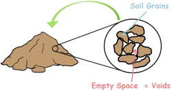
 A soil mass is composed of small solid particles which we call the soil grains. These soil grains when depositing in a soil mass arranges themselves in a way that some amount of empty space is left between them. We call these spaces voids.
And the property of the soil which permits the water or any liquid to flow through it through its voids is called permeability. Permeability is the ease with which water can flow through the soils.
For many engineering projects we need to know the permeability of the soil as it is a very important engineering property.
There are numerous methods through which we can measure the permeability of a soil in the field or of a representative sample in the laboratory.
We have already discussed laboratory methods.
 Permeability of the soil in its natural deposits is highly influenced by its natural structural factors such as non-homogeneity and stratification. So it is not possible to take out a soil sample which may represent the true in-situ structure of soil to be used in laboratory. Also for coarse grained soils, in which permeability values are very significant, it is very difficult to obtain undisturbed sample.
So to deal with such problems and to obtain a near accurate value of permeability we perform field tests on soil mass.
Usually pumping out test is conducted for the purpose. We perform these tests for large engineering projects because these tests are very expensive.
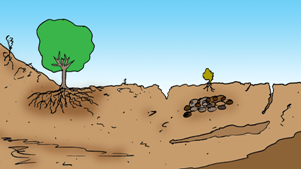
Pervious soils in the ground are the reservoirs of the ground water. Their voids work as a storage and passage for the water. Such an underground layer of permeable rock or unconsolidated materials such as gravel, sand or silt is called an Aquifer. It is a body of saturated rock through which water can easily move.

The Ground water from an aquifer can be easily pumped out.
In the nature we usually encounter two kinds of aquifers.
1. Unconfined Aquifer
2. Confined Aquifer

Unconfined Aquifers
Unconfined Aquifers simply means an aquifer that does not have a confining layer between it and the ground surface. Water can flow directly between the surface and the saturated zone of the aquifer.
An impervious layer may present under the aquifer but not above it.
The water level in unconfined aquifer remains at the atmospheric pressure. These aquifers are sometimes also called water table aquifers, because their upper boundary is the water table.
Confined Aquifers
But sometimes this porous water holding layer is confined or sandwiched between two impervious layers of soil and the aquifer is bounded at the top and bottom by relatively impermeable strata. These kinds of aquifers are called confined aquifers.
In such aquifers water cannot enter or leave by vertical flow because of these impermeable soil layers. These impervious layers of soil are called aquicludes and these are often made up of clay soil.
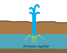
Under such conditions water may also be present in the pressurised state. When a well is drilled into such aquifer, the internal pressure pushes the water up in the well and in some cases water even comes up to the surfaces completely out of the well. This type of well is called Artesian Aquifer.
For both confined and unconfined aquifers permeability calculations will be slightly different. We have already discussed the permeability of unconfined aquifer and now we will discuss the permeability of Confined Aquifer.
In confined aquifers water remains in pressurized state so the water level of the aquifer is not its hydraulic head. Because we know total head or energy of the water is the height of the water column plus its pressure head plus velocity head.
 Velocity of water inside the soil being very small velocity head is neglected and energy of the water only remains its height and pressure.
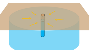
So the actual energy of the water can be measured by inserting a piezometer at any point in the aquifer and reading the piezometric head or making an observation well into the aquifer and measuring the water level in it.
We may draw a piezometric surface or energy surface above the aquifer which may indicate the hydraulic head of the aquifer. We can notice this is above the actual water level.
In order to measure the permeability of such aquifers we employ pumping out method. Pumping out method involves making a well into the ground that reaches the aquifer and penetrates it throughout its whole thickness. It is important that well penetrates the entire thickness of aquifer. It is called test well.

Water is pumped out through this well and as a result pressure of water starts releasing and piezometric level starts decreasing. The piezometric surface of water which may be horizontal initially is then acquires this kind of shape that is called cone of depression.
We can observe this by making two observation wells at some distance from the test well. We can measure the difference of water levels in them before and after the water has been pumped out of the test well.
When the water is pumped out a hydraulic gradient is formed inside the soil mass because of the piezometric profile generated. The height of the piezometric level at any point is the hydraulic energy or hydraulic head of the water at that point.
 We know water flows from high hydraulic head to low hydraulic head. The water level in the well may by higher than its surrounding but it has lower head than its surrounding. So water will flow from all directions of high head into the well of low head. If we imagine it in 3D then we can see the flow is radially inward from all directions.
Hence when we pump out the water from the well, the water in the aquifers moves towards the well and starts refilling it.
But still we continue the pumping of water till the steady state of flow is reached.
The steady state of flow is reached when the amount of water pumping out from the well becomes equal to the amount of water refilling the well. So rate of water radially crossing in any cylindrical surface area surrounding the well is equal to the rate of water entering into the well.

At this state water level in the well will not change. In such a state the drawdown curve becomes constant and the water level in the observation wells is also becomes constant.
So let at this steady state, the height of the water level in the first observation well is z1 and it is at a distance of r1 from the centre of the test well.
Similarly the height of the water level in the second observation well is z2 and it is at a distance of r2.
Also say the thickness of this confined aquifer is capital B.
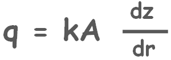
We assume that the flow of water in the soil voids is laminar so we can apply Darcy’s law for this situation. According to the Darcy’s law discharge rate from the well q is equal to the permeability of the soil multiplied by the area through which water is percolating multiplied by hydraulic gradient which is causing the flow.
q = kAi
We can see the hydraulic gradient has a curved profile, it is not constant.

So let’s assume that at some distance r from the centre of the well piezometric level is z and at a little distance dr away the height of the piezometric level increases by dz height. For such a short distance we can consider the hydraulic gradient as constant and that will be equal to the change in piezometric level divided by the distance over which the change occurred.
The area through which the water is percolating by this hydraulic gradient is this cylindrical area of radius r and height capital B which is the thickness of the aquifer. So area of this cylindrical surface is 2πrB.

Re-arrange it like this.

And we can integrate it from our observation of water level in the observation well which was at r1 distance from the test well was z1 and level in the well which was at r2 distance was z2.

After integrating
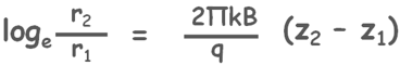
and applying limits we can find the equation for the permeability of the soil.

Assumptions :
We should keep in mind that in obtaining this value of the permeability of the soil we have assumed certain things.
First we assumed that the water flow inside the soil is laminar and steady.
Second we assumed that the soil mass is isotropic and homogenous.
Third we also assumed that our test well penetrates the entire thickness of aquifer and with that we assumed that the flow of water towards the test well is only radial and horizontal and water does not enter the well from the bottom.

why do we take a cylindrical percolation area in this derivation?