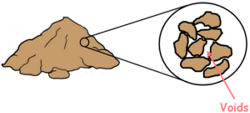
 A Soil mass is the huge collection of small particles we call soil grains. These soil grains when depositing in a soil mass encloses empty space between them which we call voids.
The free water available under the ground moves inside the soil under the influence of gravity and it flows through these voids. This phenomenon of flow of water, movement of water through the soil is called seepage.
We know that water moves from high energy state to low energy state and in case of water these energy states are represented as hydraulic heads.
The hydraulic head is the amount of mechanical energy or liquid pressure available at any point in water above datum.
For the flow of water to take place in the soil also there should be a difference of hydraulic head between two points in space and water flows from high hydraulic head to low hydraulic head.
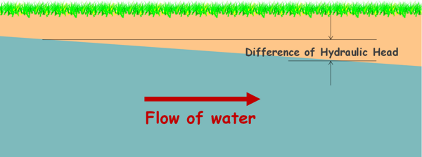
Hence we can say Seepage takes place when there is difference in hydraulic head.
Water does not flow if two points in the water have the same energy or have inadequate head difference. Water may flow even against the gravity if point A is at higher hydraulic head than that of point B.
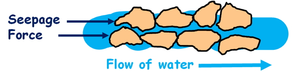
As the water flows through the soil the surface of the soil particles offers a resistance to the flow, in turn water also pushes the soil particles and applies a drag on them in the direction of its motion. This drag increases the inter-particle forces. This force applied by the water on the soil particles is called the seepage force and because of it pressure developed in the soil is termed as seepage pressure.
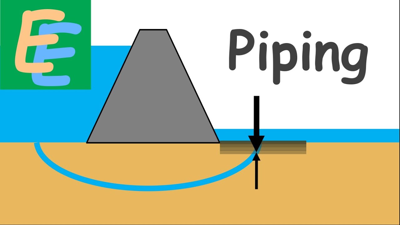
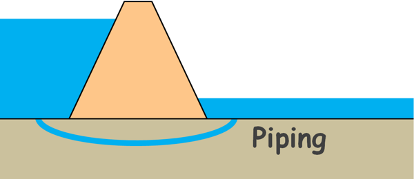
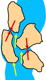
When the water flows in the soil in horizontal direction, it exerts seepage force on the soil particles in the horizontal direction. If this exerted force is strong it has the capability to displace the soil particles in its way and particles may get carried away by the flowing water. This phenomenon leads to a very serious problem in the soil engineering, development of channels in soil and this phenomenon is called piping.
But here, we will discuss only the flow of water in the vertical direction. When water flows in vertical direction it has direct impact on effective stress acting on the soil particles.
And what is effective stress?
Soil particles in a soil mass are burdened by the weight of everything above them which includes weight of all the soil particles above them, weight of water and weight of any structure if present above; and because of this weight these particles experience stress which we call total stress.
This total stress is shared by the two components in the soil mass.
Part of the stress is shared by the water present in the voids of the soil structure and that is called pore water pressure.
And the other part of the stress is shared by soil grains by their grain to grain force transfer at their point of contact and that is called the effective stress. It is the part of the total stress that is acting on soil particles.
So total stress is equal to the sum of effective stress and pore water pressure.
σ = σ’ + u
And the expression for effective stress is written as total stress minus pore water pressure.
σ’ = σ – u
Stress at any plane under the soil can be given as force on that plane divided by the area of the plane.

Force on that plane is the weight of soil above the plane and that is unit weight of soil multiplied by its volume. Volume is area multiplied by the height of the soil mass.
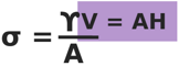
This can be simplified to this:
σ = γH
 So we can directly write the stress under any material as unit weight of the material multiplied by the height of the material above that point.
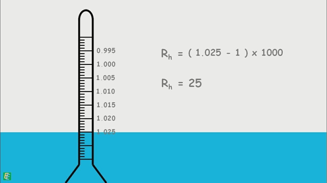
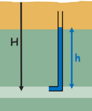
Pore water pressure at any depth in the soil can be measured by inserting a standpipe at that point and observing the height of the rise of water in the column. Pore water pressure will be the unit weight of water multiplied by height of the water column.
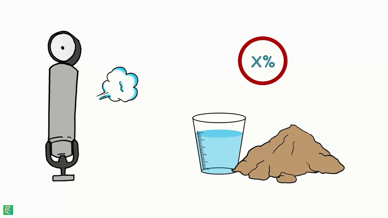
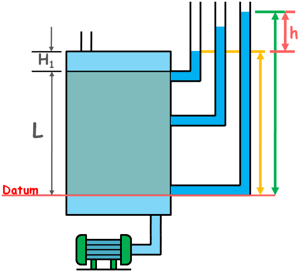
To analyse the effect of seepage on effective stress, we take a soil sample of say length L and cross-sectional area A. The sample is placed in a tank type container that has valves at its top and bottom. First we keep the bottom valve closed and completely fill the container with water so as to submerge the soil. As the bottom valve is closed no water flows through the soil hence no seepage occurs. When water does not flow and remains stagnant in the soil the condition is known as hydrostatic condition.
We insert the standpipes at different depths in the soil and notice that water has risen in all the pipes up to the same elevation. But the height of rise is different for different pipes. We know the height of the water column represents the pore water pressure in the soil at that depth. So pore water pressure is different at different depths.
It is the total head, which is the sum of pressure head and elevation head, which is equal for all the depths in the soil in our hydrostatic condition, not the pore water pressure.
If we consider the bottom of the soil sample as our datum and measure elevations of the points of interest, we can see the sum of elevation head and pore water pressure is same at all depths that is total head is same; and when total head is same everywhere, water does not flow in any direction.
The total stress, pore water pressure and effective stress at different depths can be calculated for this no flow condition.
Let’s say height of the water above the soil sample is of height H1.
Total stress at the surface of the soil would be because of water above
σ = γwH1
Pore water pressure will be γw and height of the water column in standpipe, H1
u = γwH1
So, effective stress is zero.
σ’ = σ – u
σ’ = 0
Similarly, at the bottom of the soil sample total stress, because of water, γwH1 and because of saturated soil, γsat multiplied by L, length of the soil sample.
σ = γwH1 + γsatL
Pore water pressure because of the whole water γw multiplied by the height of the water column in the standipe, which is length of the soil sample L plus height of the water above H1.
u = γw(L + H1)
Hence effective stress is.
σ’ = σ – u
σ’ = (γwH1 + γsatL) – (γw(H1 + L))
σ’ = (γsat – γw) L
we can write it into submerged unit weight of soil
σ’ = γ’L
These are the effective stresses at top and bottom of the soil when no seepage occurs in the soil.
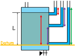
Now open the valve at the bottom and let the water flow through the soil. The valve at the top is attached with a water source so as to maintain a constant level of water in the soil tank. This condition when water is not stagnant and it’s flowing in the soil is known as hydro-dynamic condition.

We observe the standpipes and notice that the water level in the tubes has been altered. It is not the same in all the tubes as it was earlier in case of hydrostatic condition. It is now different in different tubes.
The total head, that is pressure plus elevation head, at the top of the soil is higher and lower at the bottom of the soil. This difference of head at different depths in the soil clearly indicates that there is flow of water in the soil, as we know water flows from high head to low head.
Let’s say the head difference between the entry head and exit head of water is small h.
Total stress distribution at different depths in the soil does not change by the flow of water as there is no change in the overburden pressure.
Total stress at the surface of the soil is stress because of water:
σ = γwH1
Pore water pressure will be γw and height of the water column in standpipe H1.
u = γwH1
So effective stress is zero.
σ’ = σ – u
σ’ = 0
Total stress at the bottom of the soil is stress because of water γwH1 plus stress because of saturated soil γsatL.
σ = γwH1 + γsatL
Pore water pressure at the bottom plane is γw multiplied by the height of the water column in the standpipe, which is the total length of the soil and water (H1 + L) minus head loss small h.
u = γw(H1 + L – h)
Hence effective stress is :
σ’ = σ – u
σ’ = (γwH1 + γsatL) – (γw(H1 + L – h))
σ’ = (γsat – γw)L + γwh
and it can be written as submerged unit weight of soil.
σ’ = γ’L + γwh
We know the change in the hydraulic head per unit distance over which this change occurs is called hydraulic gradient.
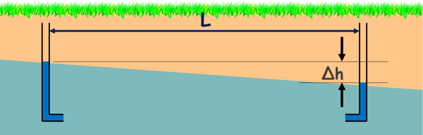
In our case the head loss over the length of the specimen L is small h. So the flow is taking place in a downward direction under a hydraulic gradient say i.
If we are to represent it in hydraulic gradient, we can simply write it iL from this equation.
σ’ = γ’L + iLγw

We wrote it this way because to calculate the effective stress at any depth in the soil we don’t need to insert an additional standpipe at that depth and measure its head loss, as it has been removed from the equation. Hydraulic gradient throughout the soil is constant so effective stress at that depth z can be given as this.
σ’ = zγ’ + izγw
If we compare this effective stress at the bottom of the sample with the effective stress in the hydrostatic condition at the same level, we can see the effective stress has increased by iLγw. This increased stress or pressure is called Seepage Pressure.
It clearly indicates that downward seepage in the soil increases the effective stress or inter-particle forces. This additional stress is due to seepage pressure which acts in the direction of flow of water. When water flows down the soil mass water tends to push soil particles downwards. Consequently soil particles push each other causing to increase the inter-particle forces and that is increase in effective stress.
So the increase in effective stress at any point below the surface at a depth z when water is flowing with a constant hydraulic gradient i can be written as izγw.
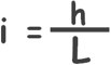
Now let’s reverse the situation and attach the water source to the bottom valve.
 Now the flow of water in the sample is in upward direction, an upward seepage is taking place.
We notice piezometric levels in the standpipes have changed and total head at the bottom of the soil has now become greater than the head at the top.
Let’s say that the head difference between two ends of the soil are small h, so hydraulic gradient that is responsible for moving the water in the upward direction is
Let’s analyse the stresses again.
Effective stress at the top surface is again Zero.
Now at the bottom surface total stress is because of this water is γwH1 plus because of the saturated soil γsatL.
σ = γwH1 + γsatL
Notice that total stress is unchanged.
Pore water pressure is γw multiplied by the height of the water column in the standpipe which is the total length of soil sample and water (H1 + L) plus head difference small h.
u = γw(H1 + L + h)
Hence effective stress can be written as this:
σ’ = σ – u
σ’ = (γwH1 + γsatL) – (γw(H1 + L + h))
σ’ = (γsat – γw) L – γwh
and it can be written in submerged unit weight of soil.
σ’ = γ’L – γwh
and head difference can be written as iL.
σ’ = γ’L – iLγw
 Now comparison with the previous conditions shows that the upward seepage in soil reduces the effective stress at the bottom of the soil by iLγw.
When water flows upwards in soil it tends to push the soil particles in upward direction. Consequently soil particles are lifted against gravity that causes to decrease the inter-particle forces and that we say decrease in effective stress.
Now if we notice that if head difference h keeps on increasing it may reach a condition when seepage pressure (iγwL) in the equation becomes equal to γ’L. At that point effective stress in the soil will become equal to zero.
γ’L – iγwL = 0
We can solve it for the hydraulic gradient at which effective stress in soil reaches to zero.

This hydraulic gradient is called critical hydraulic gradient and is written as icr.
When water flows in the soil in upward direction at the critical hydraulic gradient, the seepage force or drag exerted by water on soil particles, which pushes them up, completely balances the weight of these particles, and they seem to be suspended in water.
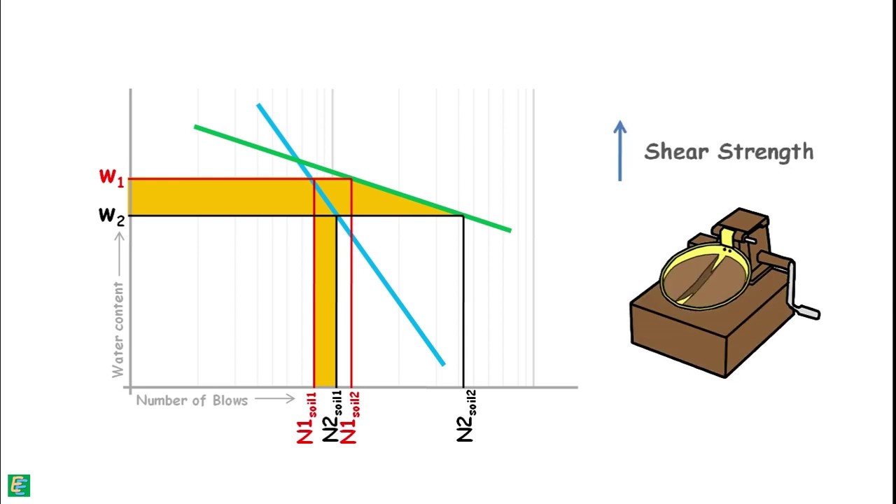
Soil in such state does not behave like a soil any more but behaves like a very viscous liquid. Soil loses all its shear strength and is no longer able to support any load.
This phenomenon is called Quicksand.
Note that Quicksand is not a type of sand, it is a hydraulic condition.
If we remember, we learned a relationship of soil parameters.
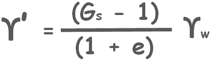
This relationship relates unit weight water with the properties of soil that are soil’s unit weight, its void ratio and specific gravity of its solid particles. We can re-write it
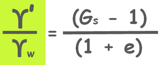
and substitute this as critical hydraulic gradient.
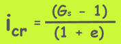
It is an important relationship to be remembered. If we know specific gravity of soil particles in a soil mass and its void ratio we can calculate the critical hydraulic gradient for that soil, gradient at which the movement of water in upward direction in the soil is such that the soil becomes quick and loses all its shear strength and is not able to support any load.
 We have seen in some movies that humans sink into the quicksand and die. But theoretically it is not possible for a human to sink completely into quicksand because human mass density is lower than that of the quicksand soil. A human may only sink up to about his waist only if he does not panic. But if one panics he may fall into the sand and won’t be able to stand back up and that he may die because of suffocation. So never panic if you are trapped in a quicksand. Stand still and call for help. In the meantime also pray that Elementary Engineering knowledge sources were correct.
Quicksand condition is also called boiling.
This upward seepage force mainly affects fine sands and silts. It is less prominent in clay soils. Because First clays have poorly connected voids and flow of water is not as facilitative as in sand. And second clay particles possess cohesion which holds the grains together even at the critical hydraulic gradient.
Boiling does not occur in coarse sands and gravels either, because to lift gravel particles against gravity large water discharge is needed.
Seepage Force
Seepage pressures can also be written as Seepage force, that is the force applied by the flowing water to the soil structure. We know force is equal to pressure multiplied by area.
so seepage force is equal to seepage pressure multiplied by the area of the soil sample is capital A.
J = iLγwA
It is represented by capital letter J.
But seepage force is usually expressed as force per unit volume.
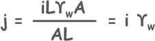
It is represented by small letter j.
Take a look at an example of this understanding.