A dam is a barrier that restricts the flow of water and can be used to collect the water. This water may be utilized for many purposes such as irrigation, human consumption, industrial use and hydro power generation.
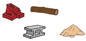
Dams can be created using different materials such as bricks, concrete, timber and earth that means soil. Different sites require different types of material for the construction of dam. Not all the sites are appropriate for the construction of all the types of dams but an earth dam can be designed to be constructed at almost any site.
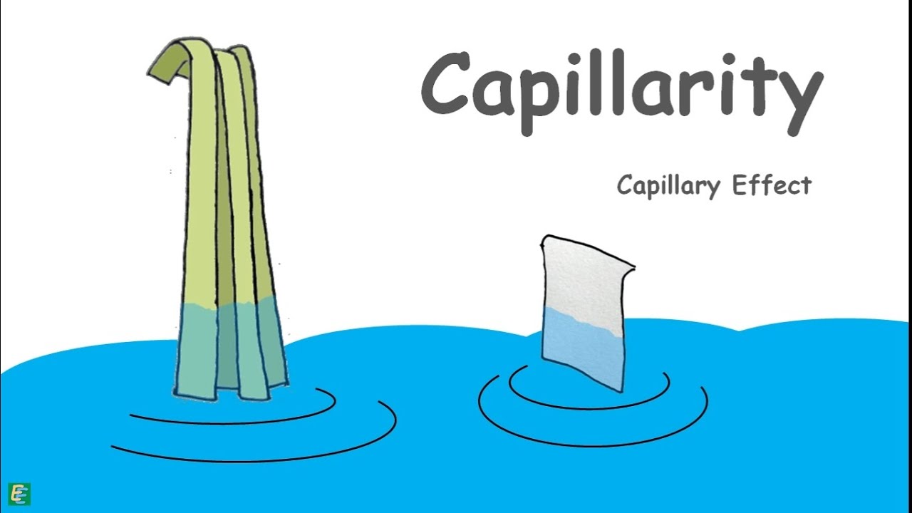
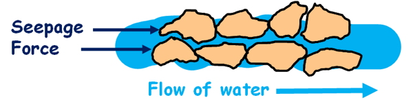
In earth dams the construction material is earth that is rocks and soil. The water that an earth dam holds on its one side flows from upstream through the voids present in the soil of the body of the dam to downstream by the action of hydraulic head difference. This phenomenon of flow of water, movement of water through the soil is called seepage.
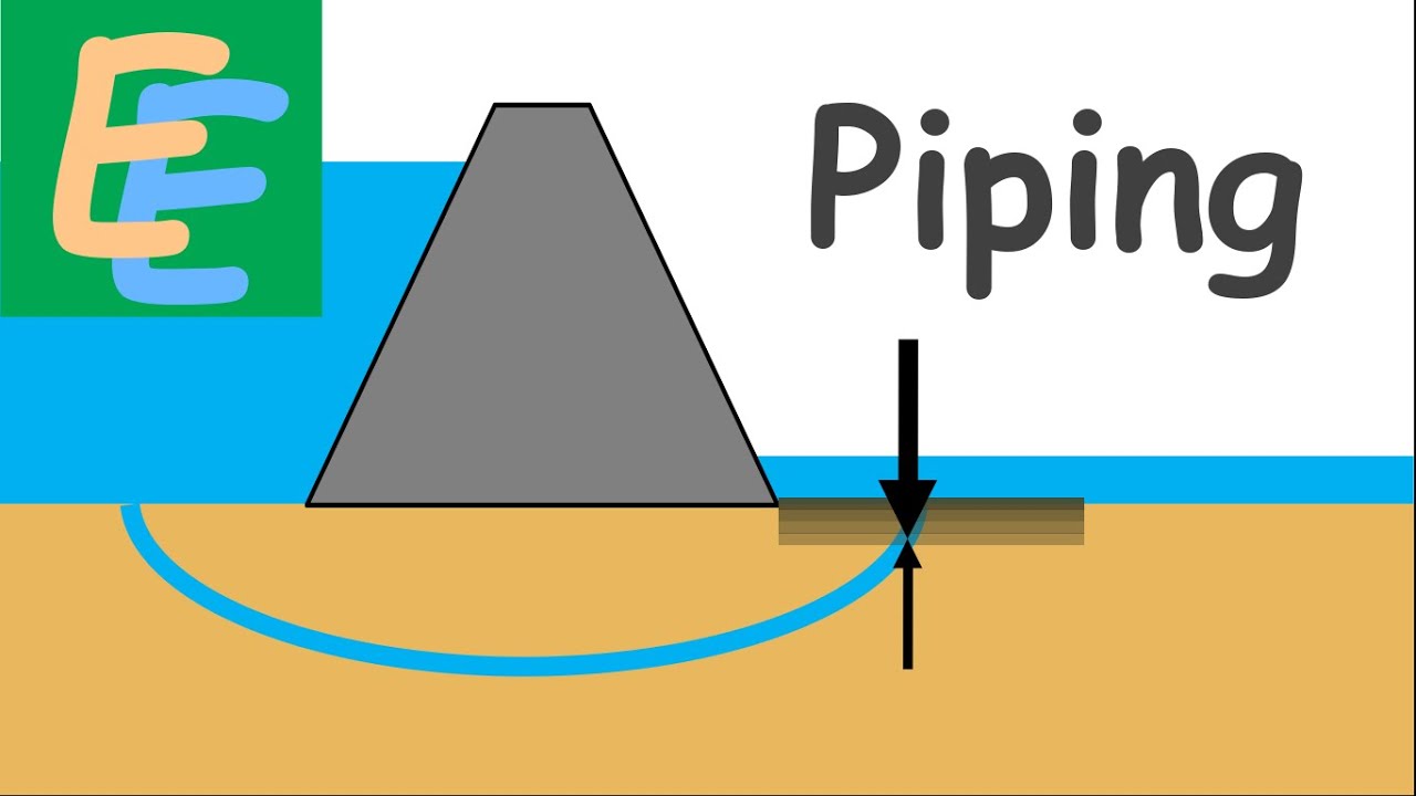
As the water flows through the soil it exerts a drag on the soil particles in the direction of its motion. If this exerted force is strong it may displace the soil particles in its way and particles may get carried away by the flowing water.
 This creates pipe like openings in the body of the dam through which water can flow rapidly. This phenomenon is called piping. It is one of the major causes of failure in earth dams.
We have already discussed the different types of piping failures.
To construct an earth dam we need huge amount of soil. So we use the soil that is easily available near to the construction site as it is not economical to transport this much quantity of soil from a distant source.
Depending upon the type of soil available near the site and used for the construction of an earth dam they are broadly divided into three categories.
Homogeneous Dam
If fine grained soil is available in abundance near the construction site then the whole dam can be constructed with it because fine grained soils are relatively impervious and are more effective in holding back the water.
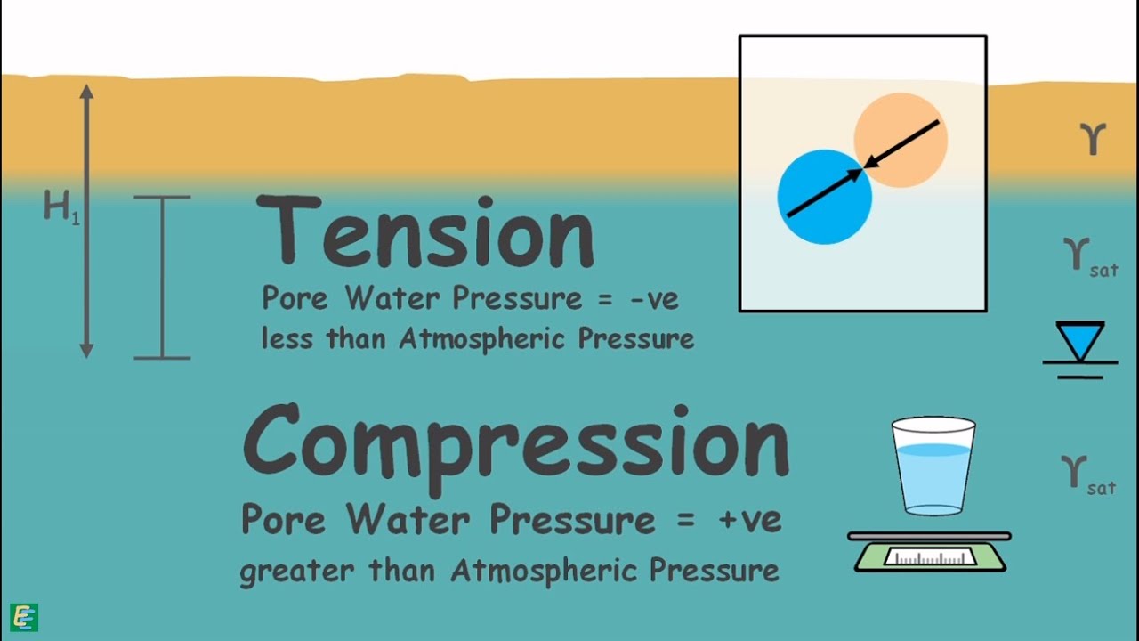
Still some water will seep through the body of the dam and this water may cause to generate high pore water pressure at the exit point on downstream slope causing the soil particles to get removed with the flow of water.
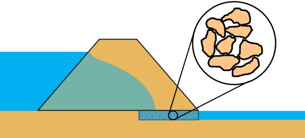
So to channelize the water out of the dam in a controlled manner we provide a horizontal blanket drain at the base of the downstream part of the dam that is made up of coarse grained soil.
Thin Impervious Core
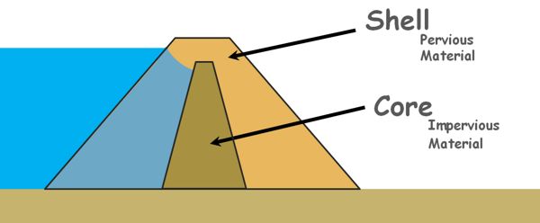
If impervious soil is not available in large quantity near the construction site but pervious soil is in abundance then the outer shell of the dam is constructed with pervious soil and in the middle of the dam a core is constructed using the impervious soil.
The Impervious material holds back the water and the pervious material of the shell provides support to the core.
Zoned Dams
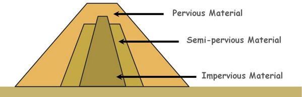
When all types of soils are available in good quantity near the construction site we construct the dam in zones of different kinds of soils.
We keep the zones of pervious soils in the dam exterior and impervious soils in the dam interior. In not so critical zones of the dam we may place semi-pervious soil.
Practically dam sections are not this simple but we can point out few basic components of the dam that are required in the design of an earth dam.
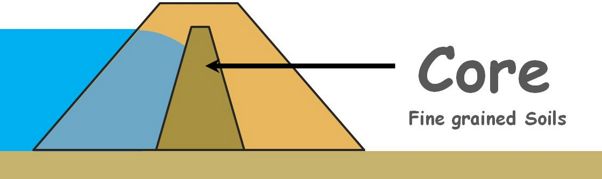
1. core It is made up of fine grained soil. Its purpose is to control seepage through the dam.
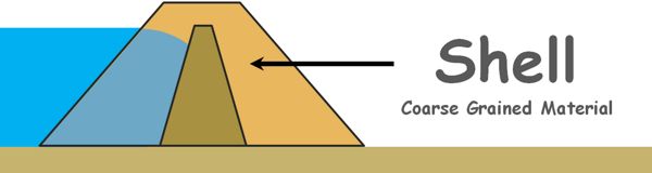
2. Shell It is usually constructed with coarse grained material. The shell provides stability to the dam.
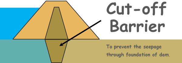
3. Cut off barrier beneath the dam. This prevents seepage through the foundation of the dam.
4. Transition filters between zones of different soil materials. We cannot place very coarse grained soil right next to very fine grained soil because fine particles of the fine grained soil will migrate through the voids of coarse grained material and may get washed out of the dam.
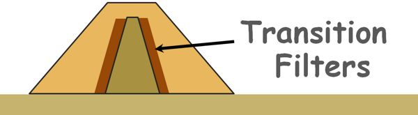
The transition filters are so designed that they are more permeable than the soil they protect and yet their particles are not so coarse that the fine particles of the protected soil can move and travel through the voids in the filter.
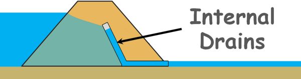
5. Internal drains An internal drain may be horizontal, vertical or inclined. Its purpose is to intercept the seepage flow and prevent it from exiting from the downstream slope of the dam. Drains are made using sand or gravel sized particles. Gravels can be viewed as a medium of effectively infinite permeability in comparison to the dam material, so this enable the water to flow through drains without any significant loss of head and that water can be carried out of the dam in a safe manner.
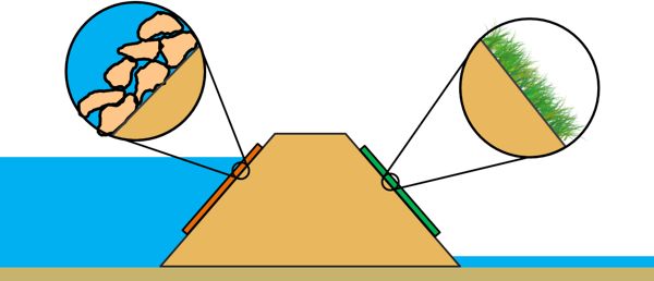
6. Protective layers on the upstream and downstream slopes. The upstream slope of the dam may get washed away by the wave action of water in the reservoir and the downstream slope may get washed away by the heavy rain.
The protective layer that may be made up of big rock such as boulders and cobbles or simply of grass or vegetation, prevent the slopes to get eroded.
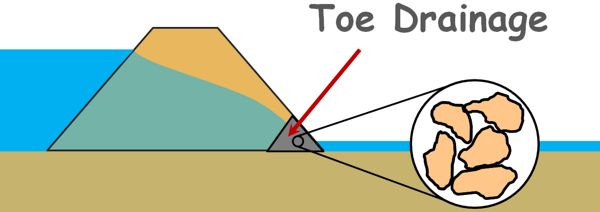
7. Toe drainage All the seepage water exits at the toe of the dam and therefore it is usually always wet. It is made using cobbles to boulders size material.
It is difficult to construct an earth dam with zero seepage. Some of the water will always seep through the dam and the foundation. So for the safety of the structure against piping the seepage through it must be within acceptable limits.
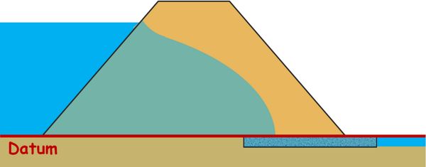
Let’s try to estimate the amount of seepage losses through the body of a homogeneous earth dam having a horizontal filter at the downstream end. We also assume that foundation of the dam is impermeable and water will only seep through the body of the dam. So the bottom surface can be taken as datum.
One of the methods to estimate this quantity of water seepage is flow net.
We have already discussed the method of flow net construction when the flow was confined that means all the boundary conditions of the flow were known to us.
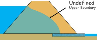
But seepage through an earth dam is the case of unconfined flow of which the upper boundary is not known.
So we begin with what we know and then we will try to find out the missing boundary condition and construct our flow net.
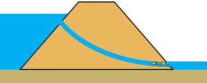
Let’s say the upper boundary line represents the top flow line. All the seepage through the dam occurs below this line.
Also let’s name few points in the diagram.
Let’s say the height of the water level to the side of the dam is small h.
Here we can see total head at each point of the upstream face AB up to the AG is same and that is equal to h. Hence each point on this line AG is at equal potential so AG is an equipotential line.
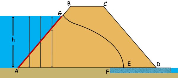
The bottom surface of the dam is the impermeable boundary. Water cannot cross it but may flow along it from upstream face to the filter. Hence this bottom impermeable boundary AF is a flow line.

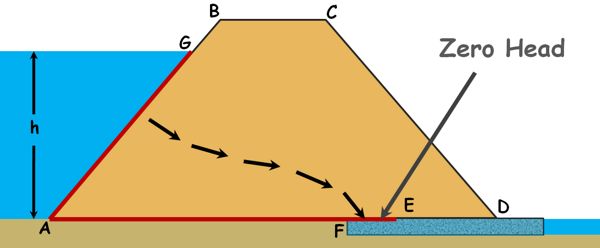
When water exits from the filter it has zero pressure head and zero elevation head, hence pressure along the filter is same and that is equal to zero. Hence the discharge face EF is an equipotential line.
The fourth boundary of this flow is this top flow line GE. This line is called phreatic line or seepage line. The soil is saturated below this line and pressure on this line is atmospheric.
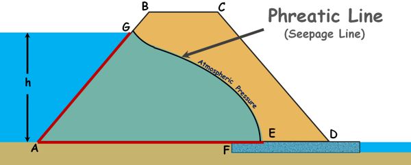
Casagrande observed that the shape of this top flow line is close to a parabola for most of its length and deviates from parabola only at the upstream and downstream faces. So he recommended that the seepage line in actual dams can also be taken as basic parabola and necessary corrections can be made at these faces manually so that it conforms to basic conditions of the flow net, such as flow line should be perpendicular to the equipotential line.
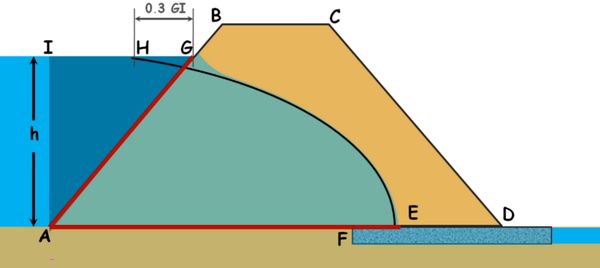
He also recommends that this seepage parabola curve starts from a point H on the upstream. If we take the horizontal projection of the wet upstream face of the dam on the water surface as GI, then the distance of this point H from the point G on the face of the dam, GH is given as 0.3 times GI.
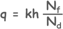
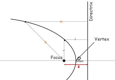 We know parabola is the locus of all the points that are at equal distance from a fixed point, called the focus, and a line, called the directrix. Distance between focus of parabola and its directrix is usually denoted as s.
This point, say, point 0 on the parabola is called the vertex of the parabola. This point O, which is also the origin, is on the curve so by definition it must be equidistant from the focus and directrix.
Let’s try to write the equation of this parabola.
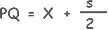
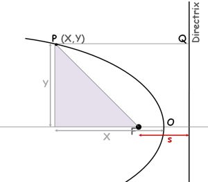 We know distance of any point P on the parabola from the directrix and its focus will be equal. Let’s say co-ordinates of point P are X and Y. We can see the distance PQ is equal to the co-ordinate of point P, X plus this distance which s/2.
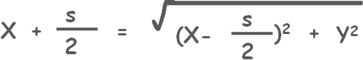
Now the distance PF can be written using Pythagoras theorem as square root of square of this distance plus square of Y co-ordinate of point P.

Now we know that PQ is equal to PF.
![]()
Solving this we get a simpler equation of our parabola curve:

If we assume the seepage line as the parabola it will be equation of the seepage line.
Let us try to draw the top seepage line using what we know.
We have named few points in the diagram and also have identified three boundary conditions. We also know the starting point H of the parabola at the upstream from where the parabola starts.
Focus of the parabola formed by the seepage line in the dam is defined as the point where bottom flow line meets the last equipotential line.
The top flow line meets the filter at the point E which is the vertex of the parabola curve. The distance between focus and vertex is equal to the distance between vertex and parabola’s directrix, and we can have our directrix.
Now that we already have two points H and E that are on parabola, we may obtain additional points to draw the curve by the property of the parabola that any point on the parabola is at equal distance from the focus and directrix.
To obtain a point on the parabola lets draw any vertical line through any point say J. Take the distance between this line and the directrix as the radius and keeping the F as the centre draw an arc that cuts the vertical line.
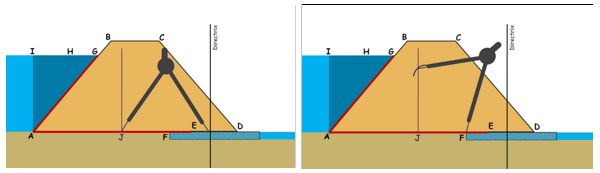
The intersection of the vertical with the arc will give a point that will be on the parabola because this point is at equal distance from focus and the directrix of the parabola.
Similarly we can obtain many points and construct the parabola for the top flow line. Once the parabola is drawn, we have to make corrections for the flow net conditions. We draw a perpendicular line to the upstream face AB at point G, from where the top flow line originates and gradually blend it into the parabola curve manually.

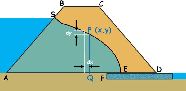
Now, we have established the top flow line which was our last and unknown boundary condition for the flow. Now we can draw the flow net for the seepage flow by the method we have discussed in the flow net topic and the seepage quantity can be calculated using this formula.
We can also calculate the seepage quantity with the geometry of the flow. Let us consider any section of the flow and name it PQ.
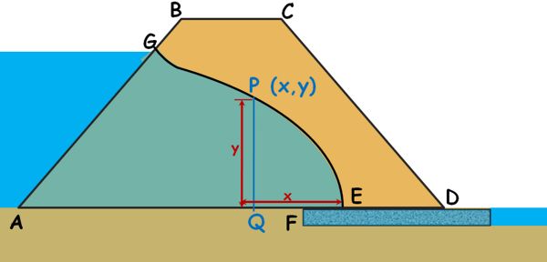
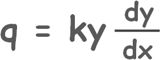
As we know the flow of free water through the soil is governed by the Darcy’s law, we can write discharge through this section as
q = kAi
If E is the vertex and origin of the parabola and co-ordinates of point P is x,y then height of this PQ section which is at distance x from origin is y. Let us imagine the width of the dam is 1 meter. In other words we take width of this section as 1 meter and we calculate the discharge through per unit length of the dam.
So area can be written as this
A = Y(1) = Y
i is the hydraulic gradient with which water is flowing through this section.
Let’s say a slight distance dx away from this section we observe a head difference of dy. So hydraulic gradient causing the flow at this section can be written as change in head over the distance over which the change occurred.

Hence we can write discharge as this.
 ….. eq. 1
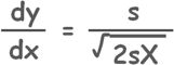
Now from the equation of parabola which we derived earlier, we can write y as this.
![]()
Differentiating it with respect to x, we get our hydraulic gradient.
Substituting both of these in equation number 1
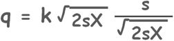
we get a simpler expression.

This simple equation gives the approximate discharge through the body of an earth dam with a horizontal filter at its downstream.
Here K is the permeability of the soil material of the dam and s can be determined using co-ordinates of the point H which is on the parabola.
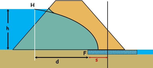
If this point is at d distance from the beginning point of the filter which is the focus of the parabola then x co-ordinate is d plus s/2; and y co-ordinate is the height of the water in the reservoir.
Substituting these in the parabola equation.

Solving this we get the value of s.