Landslides are a frightening reality that can strike without warning.
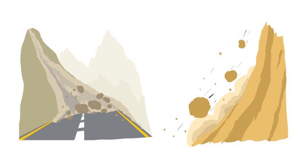
But what causes these natural disasters to happen? And why do they seem to occur more often during the rainy season.
To understand this, we must understand the concept of shear strength. In short, shear strength is the soil’s ability to resist sliding along its internal layers.
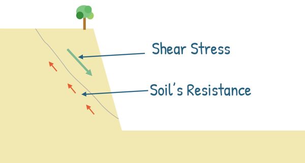
When the shear stress generated by some load or overlying materials exceeds this shear strength, failure occurs, leading to landslides.
To understand this process better, lets look deeper into the interplay of hidden forces beneath our feet. Let’s explore the concepts of shear strength and the Mohr-Coulomb’s theory.
When a material, like soil, is loaded with external pressure, it develops an internal resistance to counteract the applied force. This internal resistance is called stress. Stress is defined as the force per unit area over which this force acts.
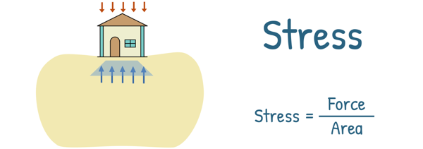
These developed stresses inside the material are of primarily two types – Normal Stress and Shear Stress.
Normal Stress is the component or part of the stress that acts perpendicular to the cross-section of the material. This can cause the material to either stretch, known as tensile stress, or compress, known as compressive stress.
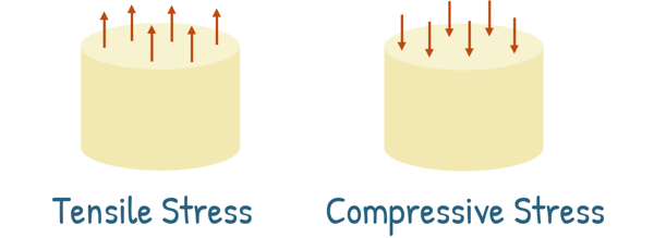
It is denoted by the Greek letter σ and defined as force per unit area, as this is a stress.
In soil engineering, we usually encounter only the compressive type of normal stresses. We have seen earlier that this compressive stress can lead to Settlement of the soil.
On the other hand, Shear Stress occurs when a force is applied parallel to the cross-section of a material, causing it to deform and slide in a shearing motion.

Shear means to cut or divide something into two parts, especially by sliding one part over the other.
So, when a material or soil experiences shear stress, the stress tries to move and slide part of the soil mass relative to the rest of the soil mass. It is denoted by the Greek letter τ and is also defined as force per unit area.
Soils are rarely exposed to direct shear forces. Instead, shear stresses often arise indirectly when soil is subjected to compressive loads. When soil is compressed, the load is transferred from one particle to another. This transfer happens at the points of contact between particles, which are often at angles. This angled load transfer can induce shear stresses along the planes where particles touch.
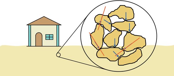
Additionally, when soil is under load, it tends to settle more than its adjacent layers, causing relative movement between them and resulting in shear stress development at the edges. Another factor is that when compressive loads are applied, the soil tends to expand sideways. This lateral expansion also creates shear stress within the soil structure.
This shear stress tries to move part of the soil mass relative to the rest by sliding. However, the soil material resists this motion. The maximum resistance that soil can provide against shear is known as the Shear Strength of the soil. When this resistance reaches its maximum value, cracks may appear in the soil, and the soil is said to have failed.
In other words, Shear strength is the capacity of the soil to resist shearing stresses just before failure occurs.
But where does this shear strength in soil come from?
Soil’s shear strength comes from three main sources:
Friction between particles: Soil particles rub against each other, creating resistance to sliding. This is particularly important in sandy soils, where densely packed particles interlock and increase friction.
Cohesion and adhesion: Some soil particles, particularly clay particles, bind together, which is known as cohesion, and cling to other surfaces, which is known as adhesion. This helps the soil resist shear stress.
Interlocking of particles: When soil particles fit together like puzzle pieces, they create a strong structure that resists deformation. This interlocking is a major source of shear strength, especially in dense, sandy soils.
But unlike other civil engineering materials such as steel and concrete, the shear strength of a soil is not a function only of the material. It also depends on the stresses applied to it and how those stresses are applied. Same soil can exhibit different shear strengths under different field and engineering conditions.
When soil is under stress, it can fail and slide along any surface. This type of failure is known as shear failure, and it is the most common way soil fails. So, it is important to look at the stress conditions at any given point within the soil to understand how and when it might fail.
When a soil is subjected to loading, it experiences stress at every point, all the way down to the bottom. At each point within the soil mass, we can imagine countless planes passing through it, each with different magnitudes of stresses acting on them. Generally, both normal and shear stresses act on each of these planes.
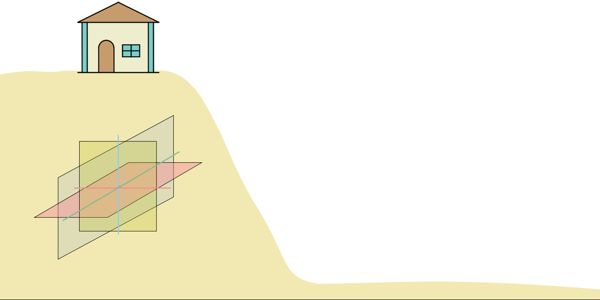
On one of these planes, if the shear stress becomes higher than the soil’s shear strength at that plane, the soil fails. This plane is called the failure plane.
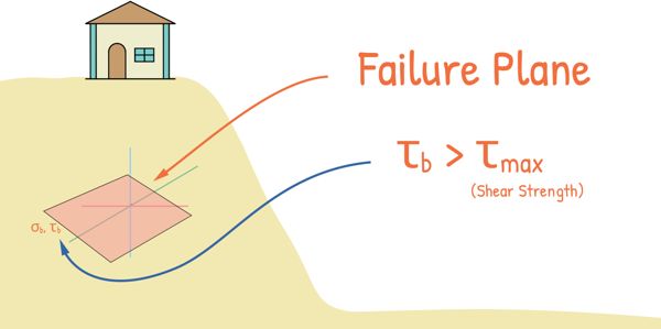
We find something interesting here: there are three planes at right angles to each other where the shear stress is always zero. These planes are called Principal Planes, and the stresses on these planes are known as the Major, Intermediate, and Minor principal stresses. These stresses are denoted as σ1,σ2 and σ3.
In soil studies, it’s often convenient and usually sufficient to consider only a two-dimensional analysis. This means we focus on the major and minor principal stresses and can safely ignore the intermediate principal stress. Even though this introduces some error, this error is typically small enough to be negligible.
At any point in the soil, lets consider a small soil element. If we know the stresses acting on two mutually perpendicular planes, we can determine the stresses on any plane that is at any angle from these two planes.
Let’s say the stresses acting on these planes are σx, σy, Txy, and Tyx. And we want to know the stresses on a plane that is at an angle θ from the plane with stress σx. The normal and shear stress on this new plane can be given by these equations:

These equations can be obtained by simply balancing the forces on the plane of interest.
 One German scientist and Civil Engineer Christian Otto Mohr realized these stresses at a point can be represented graphically. He then, developed an extremely useful device known as Mohr’s Circle of Stress.
The Mohr circle represents these equations in a manner that makes them more easily understood and remembered, and it brings out their physical significance more clearly.
To draw a Mohr circle we first rewrite the equations after a little rearrangement

and

Next, we square both sides of the equations and add them together. This gives us a new equation:

This equation represents a circle with the following form:
(σn – a)2 + (τ – 0)2 = R2
The centre of this circle is at

and its radius is given by:

To draw the Mohr circle, we plot the normal stress along the X-axis and the shear stress along the Y-axis.
We start with two given stress points: (σx, τxy) and (σy, τyx). We mark σx and σy on the normal stress axis, assuming that σx is greater than σy.
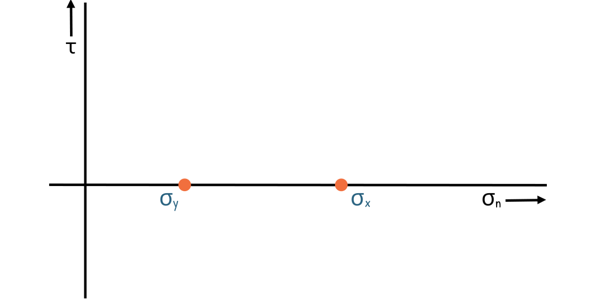
Note that τxy and τyx are equal in magnitude but opposite in direction, so τxy = -τyx. We mark these points on the graph and connect these two points to form the diameter of the circle.
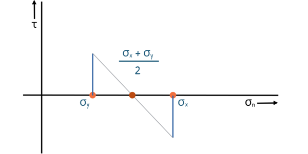
The centre of the circle is the midpoint of this diameter. We can also find the centre by calculating the midpoint of the two normal stresses on the X-axis.
With these points and the diameter, we can draw the Mohr circle. This circle always lies on the normal stress axis.
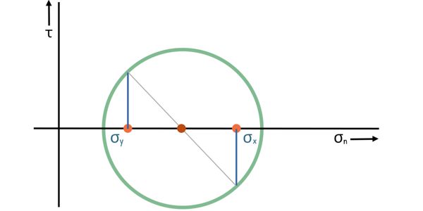
Each point on the Mohr circle represents the normal stress (σ) and shear stress (τ) acting on a particular plane passing through that point in the material.
The Mohr circle is incredibly useful for engineers. It helps in determining various stresses and provides valuable insights. The principal stresses can be easily spotted and determined, and their orientation can be easily measured or calculated. The two extreme points on the circle on the x-axis represent the major and minor principal stresses, σ1 and σ3, which are the maximum and minimum normal stresses.
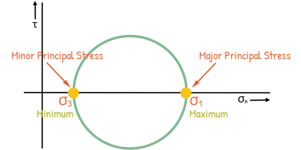
We can see that these points satisfy the definition of principal stresses because the shear stress at these points is zero.
The centre of the circle, C, can also be written in terms of the major and minor principal stresses as their midpoint: ((σ1 + σ3)/2, 0). The radius of the circle, in terms of principal stresses, can be written as (σ1 – σ3)/2.
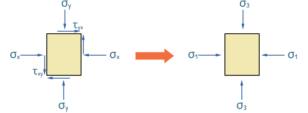
We created this Mohr circle by considering a general soil loading scenario where the soil experiences both horizontal and vertical stresses, including shear stresses. These stresses are not necessarily the maximum that the soil experiences. Therefore, to simplify the analysis and to create a scenario similar to what we recreate in the lab, we consider that the horizontal and vertical stresses are the maximum and minimum stresses that a soil sample is experiencing. Hence, these σx and σy become σ1 and σ3, respectively. So these stresses become the principal stresses, and the planes on which they act become the principal planes. We know that on principal planes, shear stresses are zero.
Using the equations, we can determine the centre and radius of the Mohr circle.
The centre of the Mohr circle is at:

And its radius is:

With these values, we can draw the Mohr circle.
We should note that any plane in the soil mass that is at an angle θ from the principal axis will have its stresses on the Mohr circle at a point that forms an angle of 2θ with the principal axis at the centre of the circle.
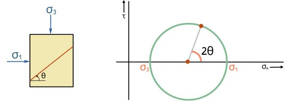
Also, We can see that the point located at the top of the Mohr circle, represents the maximum shear stress acting on some plane within the soil. It is clear from the circle that this maximum shear stress is equal to the radius of the circle. As we move in either direction from this point along the circle, the shear stress values decrease.
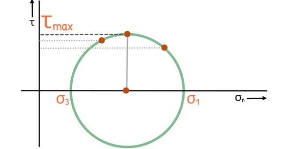
Therefore, the magnitude of the maximum shear stress that can occur on any plane in the soil is equal to the radius of the Mohr circle.

We can see that the point representing the plane of maximum shear stresses makes an angle of 90° at the centre of the circle with the point representing the principal stress. Hence, the plane makes an angle of 45° in the soil mass.
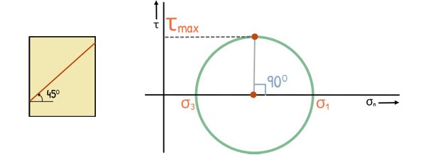
It might seem obvious that soil would fail along the plane where the maximum shear stress occurs. But, surprisingly that is not always the case.
To estimate the angle and plane of failure and the magnitude of stresses in the soil at the time of failure, several different theories have been proposed. One of these theories is Mohr’s rupture theory. This theory is widely applicable and helps us understand the failure conditions in various types of soils.
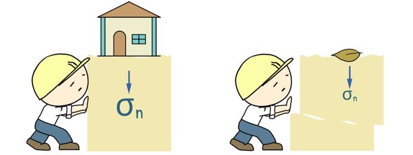
We notice that if more load is applied to the soil, more difficult will be to shear it compared to shear a soil that supports smaller load or no load at all. Hence we can see that shear strength depends on normal stress of soil, as increased normal stress on soil, increased the shear strength of the soil.
According to Mohr, failure in soil is caused by a critical combination of normal and shear stresses acting on the plane of failure. To understand this, we gather data from several tests carried out on different soil samples up to the point of failure. We then plot a series of Mohr circles, each representing the data from one test. It’s convenient to show only the upper half of the Mohr circle.
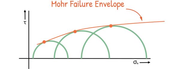
We locate the points of failure for different samples on their respective Mohr circles. A line, connecting these points and tangential to these Mohr circles, can be drawn. This line is not a perfect straight line and it is called the Mohr failure envelope. By observing this relationship, Mohr established that shear strength is a function of normal stress.

Coulomb’s earlier researches and Mohr’s investigations, found that it is safe to assume this curvy failure envelope as a straight line.
The relationship between normal stress and shear stress can be expressed as a linear equation like this.

here :
τ is the shear stress at failure,
σ is the normal stress,
c is the cohesion between the particles.
φ is the angle of internal friction, which represents the frictional resistance between soil particles.
Mohr-Coulomb’s theory accounts for both cohesive strength (c) and frictional strength (φ) of the soil.
Now, if we look at the graph, we see that the straight line – the straight failure envelope – intercepts the vertical shear stress axis at a point. This intercept represents the cohesion (c). Also the slope of this line gives us the angle of internal friction (φ), also known as the angle of shearing resistance.

From the Mohr-Coulomb theory, we can infer two key things: the Mohr circle represents the state of stress in the soil at a point, while the Mohr envelope represents the shear strength of the soil.

If the stress at a point in the soil mass creates a Mohr circle that is entirely below the Mohr envelope, the soil is safe and stable. This means the stress is within the limits that the soil can handle.
However, if the soil is stressed further – maybe due to increased load or other factors – the Mohr circle grows larger. There may come a point when this circle just touches the Mohr envelope.

At this critical moment, the stress developed in the soil has equalled the shear strength of the soil, indicating that the stress in the soil has reached the point of maximum resistance on this plane. This is the point, where cracks in the soil may start to appear, and we say that the soil has failed in shear.
Once the soil has failed, it cannot be stressed further because it will not take any additional stress and will collapse. Therefore, any Mohr circle that crosses the Mohr envelope cannot exist, as it would imply that the soil has already failed.
Using the Mohr circle, we can also determine the angle of the plane on which soil fails by shear. The angle is denoted by θf and is measured from major principal plane. It forms twice the angle at the centre of the Mohr circle. This angle can be expressed in terms of the angle of shearing resistance Φ.

From the diagram we can certainly write
2θf = 90° + Φ
and θf can be written as this.
![]()
Now, this is interesting. Soil does not fail on the plane on which the shear stress is maximum, and that is at angle 45° from the principal plane. Failure angle, θf become equal to 45O only when Φ = 0, that is, when soil provides no internal resistance due to friction and the Mohr envelope is horizontal line. This will happen in the case of the so called purely cohesive soil.

Φ is related to the internal friction that is predominant in soils like gravel and sand. This is why these soils are sometimes referred to as ‘Φ Soils‘ or ‘Frictional Soils.’ On the other hand, ‘c’ is related to the cohesion between particles, which is a main characteristic of clay soils. That’s why clay soils are also called ‘Cohesive Soils‘. Between these two types of soils lie silt soils, which can display some amount of both internal friction and cohesion. While they’re often categorized as ‘C-Φ Soils‘, their behaviour can be quite complex and varies depending on specific conditions.
Later research showed, the parameters c and Φ aren’t actually fundamental soil properties like it was initially thought. They can change based on things like water content, drainage, and how you test the soil. Also, Terzaghi figured out that it’s the effective stresses, not the total stresses, that really control a soil’s shear strength.
So the equation was re-written in terms of effective stresses as this :

where c′ is the effective cohesion and ?′ is the effective angle of shearing resistance. This equation is also known as the Revised Mohr-Coulomb’s equation for the shear strength of the soil. This is one of the most important equations of the soil engineering.
Mohr-Coulomb’s theory aligns fairly well with both field and laboratory observations of soil failure, making it a useful tool for estimating soil shear strength. However, it’s not without its limitations.
1. The theory assumes a linear relationship between shear strength and normal stress and approximates the curved failure envelope by a straight line, which in reality may be non-linear for some soils. So it might not give correct results.
2. It neglects the effect of the intermediate principal stress which may lead to inaccuracies in predicting failure plane.
3. The theory does not account for the stress history of the soil, which can significantly affect its strength and behaviour.
4. The theory assumes that the soil is isotropic, meaning its properties are the same in all directions. While soils in the field are anisotropic, which can affect their strength and deformation characteristics.
All types of slopes, be it hills, mountains, riverbanks, or even man-made cuts and fills, remain stable only if the shear strength of the material of which they are composed is adequate.
Factors such as rainfall, increases the pore water pressure in the soil which reduces the shear strength of the soil. Also it adds more weight to the soil. The combination of increased weight and reduced strength makes the soil more likely to slide, leading to landslides.


