When we look around, we may notice the roof of our home, the floor we are standing on, and when we go outside, the bridge we cross every day. All of them look perfectly straight to us.
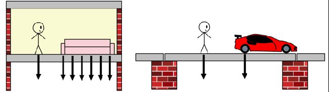
But in reality, when people walk on them, when vehicles move, when loads increase — they are never truly straight. They bend. Not enough for us to see, but enough for engineers to worry about.
But bending itself is not the real danger. The real danger is the stress produced inside the beam because of bending.
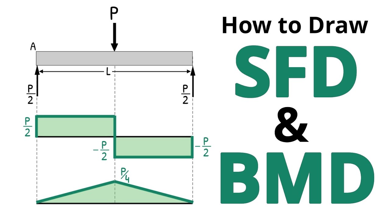
Most of these structures are supported by beams. And beams are subjected to different kinds of loading. These loads try to slice and bend the beam. But beam try to resist these forces by generating shear force and bending moment.
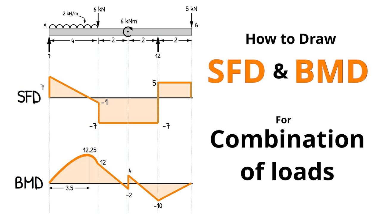
In the previous post, we learned how to calculate these internal forces and how to draw their variation along the length of the beam using shear force diagrams and bending moment diagrams.
But how do these shear force and bending moment actually come into existence?
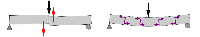
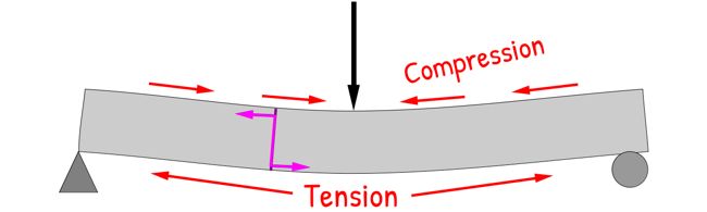
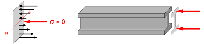
When a beam is loaded, it bends slightly. This compresses the beam at the top while stretches at the bottom. So, the fibres at the bottom of the beam are in tension, while the fibres at the top are in compression.
If we consider any cross-section of the beam, we see that the beam develops compressive and tensile stresses as a reaction to the applied load, and these stresses act normal to the section. The resultant of these stresses appears as the bending moment at that section.
We often say that bending moment generates normal stress, but in reality, it is the normal stresses that give rise to the bending moment.
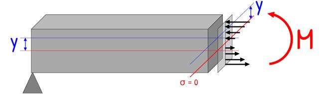
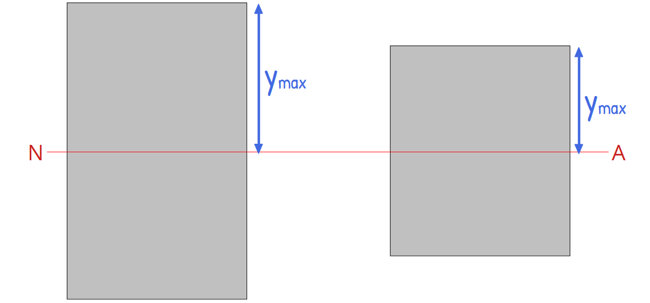
Now, if we look at the sagging beam, of which every top fibre is in compression while every bottom fibre is in tension, we can infer that there must be a plane somewhere in between where beam is neither in compression nor in tension. At this layer the stress is zero and it is called the neutral axis.
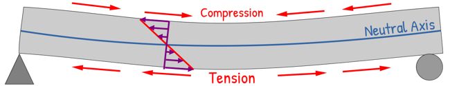
As we move away from the neutral axis, the stress increases. And at the extreme fibres — that is, the top most and bottom most layers — the stress becomes maximum.
Notice that this increase in stress is linear. This happens because, as the beam bends, the change in length of fibres increases gradually as we move away from the neutral axis. The strain, change in length by original length, naturally varies linearly with distance from the neutral axis. Now because we design our structures to remain within the Elastic Limit, the stress increases linearly.
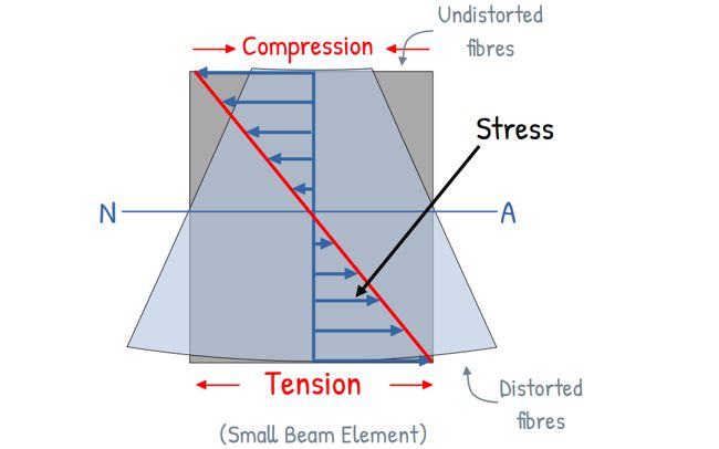
Therefore, the bending stress also varies linearly from zero at the neutral axis to maximum at the extreme fibres.
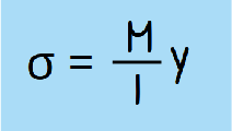
To calculate the value of this bending stress at any distance from the neutral axis, we use the flexure formula, which is given by:
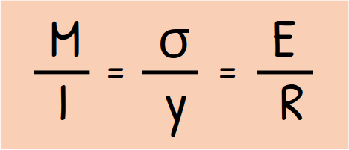
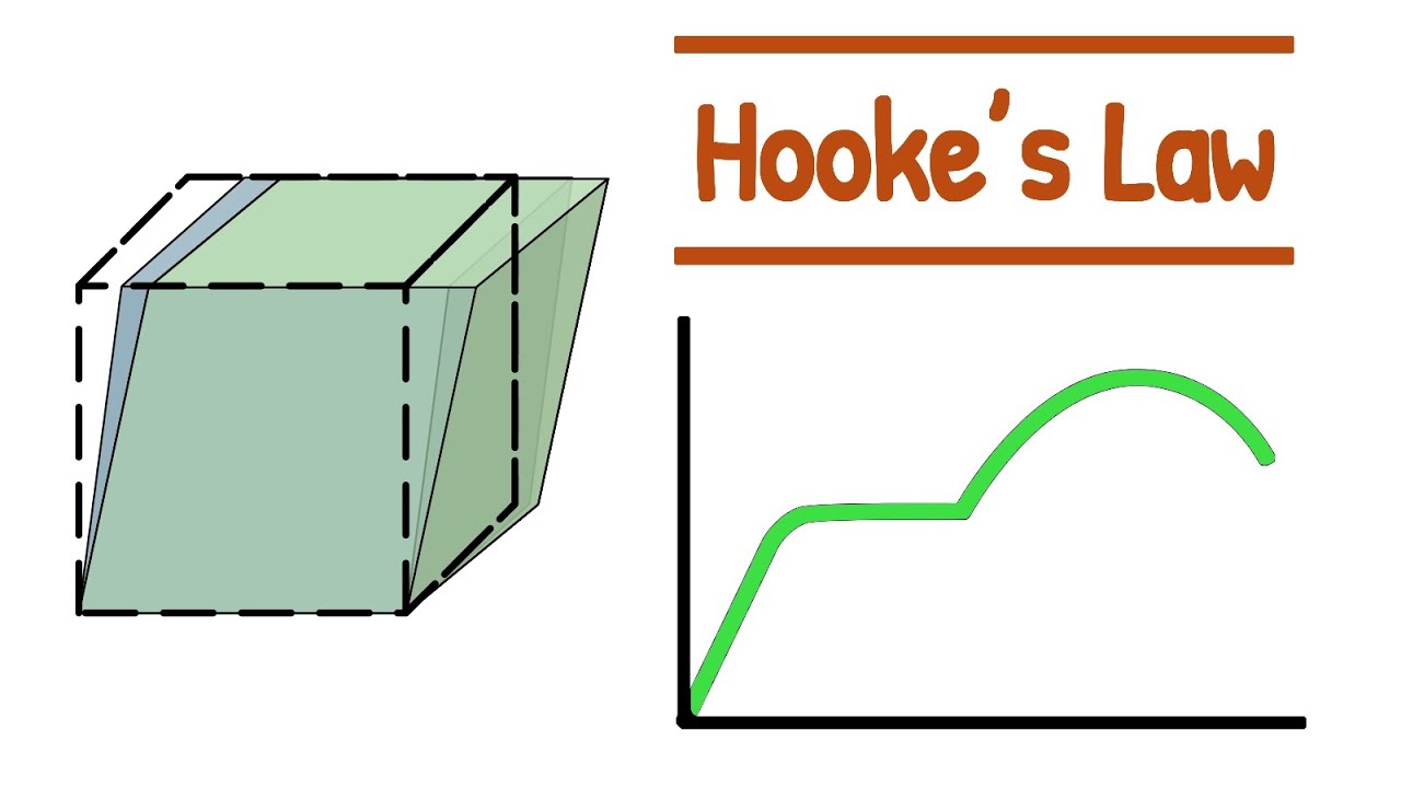
This relationship can be derived easily using the geometry of the bent beam, Hooke’s Law relating stress and strain, and and the equilibrium between internal stresses and the external bending moment.
Here
M is the bending moment at the section,
I is the moment of inertia of the cross-section about the neutral axis,
σ is the bending stress at a distance y from the neutral axis
E is Young’s modulus of the material, and
R is the radius of curvature of the bent beam
From the first part of this equation, we obtain the commonly used form of the flexure formula:
This equation allows us to determine the bending stress developed at any point in the cross-section due to a bending moment M.
We can clearly see that the bending stress is directly proportional to the distance y from the neutral axis.
So, at y = 0, that means at the neutral axis, the bending stress is zero. And as we move away from the neutral axis, bending stress increases linearly and reaches maximum at the extreme fibres.
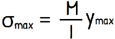
Therefore, the maximum bending stress developed in a beam section can be written as:
In practical design, this maximum stress is our primary concern — because failure, cracking, or yielding will always begin where the stress is highest.
Since the maximum stress always occurs at the outermost fibres, engineers combine I and ymax into a single property called the Section Modulus, denoted by Z.
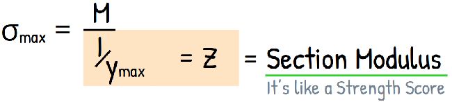
Z = I / ymax
With this, the formula becomes beautifully simple:
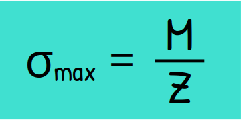
The Section Modulus is like a ‘Strength Score’ for a beam’s shape. The higher the Z value, the more resistant the beam is to bending.
This section modulus depends on distance of the extreme fibre and the moment of inertia of the section. That says, section modulus depends purely on the geometry of the beam.
And this gives us something interesting. For a given bending moment, the stress doesn’t just depend on the material; it depends heavily on the shape of the cross-section.
Now comes the most important understanding.
If we want a beam to carry more load safely, we must reduce the bending stress developed in it. And to do that we
• Either reduce bending moment
• Or increase section modulus
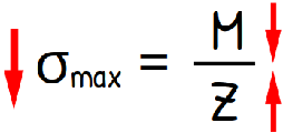
Since the loading often cannot be changed or is predetermined, we can work with geometry.
We can increase the depth of the beam. This increases the distance of material from the neutral axis. And when material is placed farther from the neutral axis, the moment of inertia increases significantly. This increases the section modulus.
A larger section modulus makes a beam stronger in bending. This is why deeper beams are stronger.
This is also why I-sections are so efficient.
The Flexure Formula tells us that the material near the neutral axis does almost no work, carries almost no bending stress — the stress there is nearly zero.
So instead of wasting material in the middle, engineers place more material at the top and bottom — where the stress is maximum.
By shifting material into the flanges, we drastically increase the Moment of Inertia (I) and the Section Modulus (Z) without adding extra weight. We are placing material exactly where it resists bending the most.
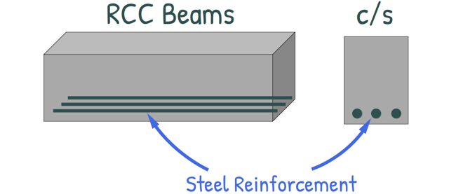
There is another powerful technique we use to strengthen beams — especially concrete beams.
Concrete is very strong in compression but weak in tension. And from our bending stress distribution, we already know that the top fibres are in compression and the bottom fibres are in tension in a sagging beam.
So, in RCC beams, steel reinforcement is placed near the bottom — exactly where the tensile stress is maximum.
So important thing to remember is this:
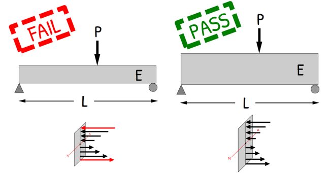
Loads don’t break structures. Stress breaks structures.
Also, shear force and bending moment do not directly cause failure, resulting stresses do.
Two beams may have same load, same span and same material, and yet one may fail while the other remains safe. Because stress inside them is different and that stress distribution depends heavily on geometry.
In this post, we focused entirely on bending moment and the stresses generated by it. But loading also produces shear force — and that generates another type of stress inside the beam. We will explore all of that in the next post.