In the early 1900s, it was surprisingly common for ships to lose their propeller shafts, right in the middle of a voyage.

And the strange part was, most of the time, it wasn’t because of a collision or even a bad storm. The shaft simply couldn’t handle the twisting forces acting on it anymore, and it failed.
So the question is — how much twisting can a shaft actually handle? And more importantly, as engineers, how do we even determine that?
Now, I used the example of a ship, but it’s important to understand: Shafts are everywhere. They are in the engine of a car, in the fan above your head, and in the giant turbines in power plants.
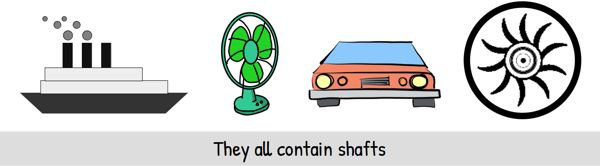
Whenever we want to move power from one place to another using rotation, we use a shaft. And if we don’t understand how much twisting it can safely handle, failure is always a possibility.
To understand this, let’s start from the very basics.
First, what is a Shaft?
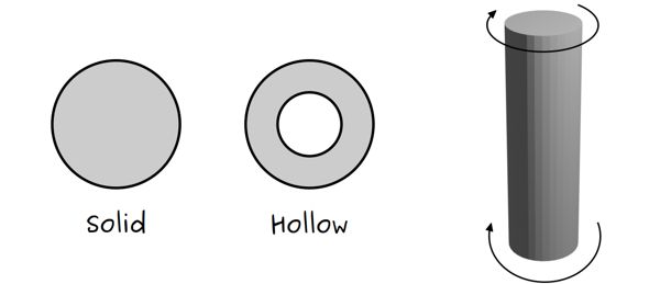
A shaft is basically a cylinder — it can be solid, or it can be hollow. And its main job in most machines is to carry rotation from one place to another.
Imagine we fix one end of this shaft so it can’t move, and we try to twist the other end. This twisting of the object is what we call Torsion. And the force causing this twist is called Torque.
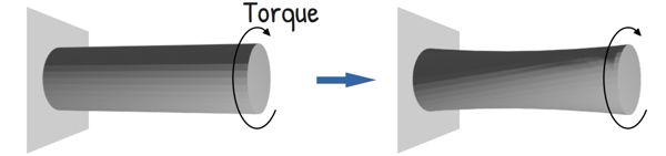
You can think of it as the rotational version of a regular force. While a regular force pushes or pulls in a straight line, torque tries to rotate or twist an object.
Now when we apply this torque, it tries to twist and deform the shaft. But the material of the shaft resists this twisting. Because of this resistance, internal stresses are developed. These stresses try to shear the material and we call them Torsional shear stresses. If these stresses become higher than what the material can safely handle, the shaft fails.
At this point, one might think, the shaft in fan or in turbine is not fixed from either end and is free to rotate. So it should be free from stress and torsion! Correct?
NO!
In reality, the shaft is connected to many other components of the machine — like fan blades or machine parts — and this extra load act as a resisting torque which creates a twisting effect across the length of the shaft, similar to a fixed-end scenario.
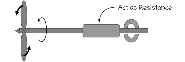
And because of this, one end tends to rotate relative to the other — which causes the shaft to twist. If the torque applied is too sudden or too strong, the shaft can fail even while spinning.
However, for our study today, we will assume the shaft is fixed at one end to keep the math simple and clear.
Imagine a grid of circular lines and straight lines along the length of the shaft. Now, when we apply torque at the free end, we see that different cross-sections of the shaft rotate by slightly different amounts along its length. We notice, circular cross-sections remain circular but the straight longitudinal lines distort into a helical shape.
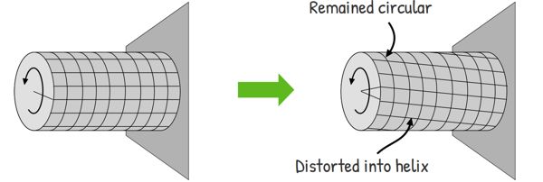
We also notice something interesting — the center of the shaft barely moves, while the outer surface twists the most. This tells us that the shaft is actually undergoing deformation, not just simple rotation.
And because of this deformation, shear strain develops in the material, which in turn causes to generate to internal shear stresses at every cross-section of the shaft.
So now the question is — does every part of the shaft feel the same stress or is it different at different points?
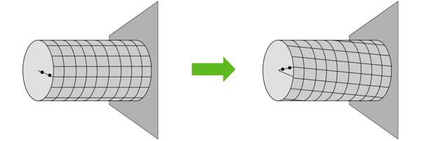
Look at the shaft, the farther a point is from the center, the more it has to move when the shaft twists. So the outer layers undergo more deformation compared to the inner layers. More deformation means more strain is developed — means they are more stretched.
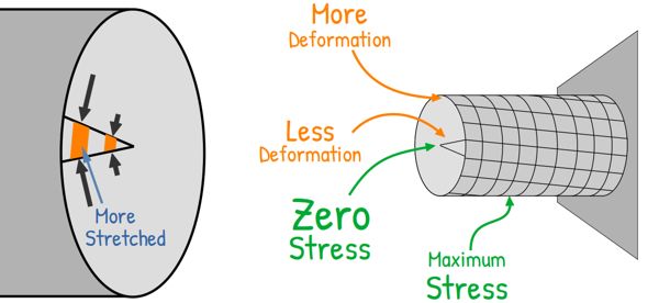
And when the strain is high, higher is the internal resistance developed — and that is what we call stress. Hence, the outer surface experiences the maximum stress. While at the center of the shaft, the deformation is almost zero — so the stress is also nearly zero.
Now, because of twisting, different layers of the material are trying to slide over each other. And whenever layers try to slide relative to each other, the stress developed is called shear stress. And since this shear stress is caused due to torsion, we call it Torsional shear stress.
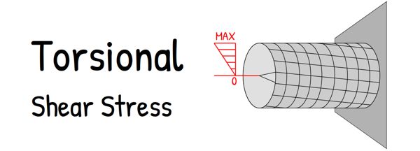
So we can say that torsional shear stress increases from zero at the center, to maximum at the outer surface.
So the outer material is doing most of the work — and also taking the most risk. That’s why, in many practical cases, failure starts from the outer surface of the shaft.
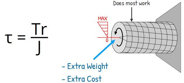
Mathematically this stress developed can be written as this:

Here,
τ = Shear stress at a distance r from the center.
T = Torque applied on the shaft.
J = is a geometric property of the cross-section, called the polar moment of inertia.
In simple terms, it tells us how difficult it is to twist the shaft of a particular shape. If more material is placed away from the center, the value of J increases. And a higher value of J means the shaft is harder to twist — so it can resist torque more effectively.
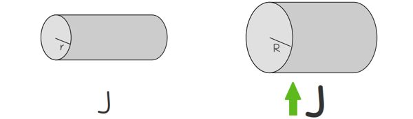
So when we increase the size of the shaft — especially its radius — the value of J increases significantly. Because for circular shafts, the polar moment of inertia depends on the fourth power of the radius. And that makes the shaft much more resistant to twisting.
The equation also tells us the same thing what we learned by looking at the diagram. As the distance from the center increases, the stress also increases. At the center, where r=0, the stress is zero. And at the outer surface, where r is maximum, the stress is also maximum.
Now that we understand how to calculate the stress inside the shaft, can we also calculate how much does the shaft actually twist when torque is applied?
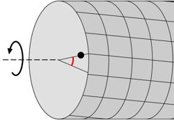
To measure this, we calculate how much any point on the shaft has rotated from its original position. This amount of rotation is called the Angle of Twist (θ), and it’s given by this formula:
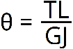
Here, θ is the angle of twist.
T = Applied torque,
L = Length of the shaft.
J = The polar moment of inertia.
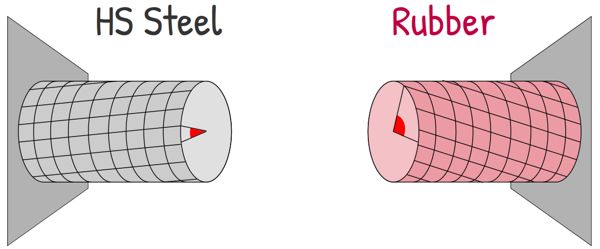
G = A property of the material, called the modulus of rigidity.
It tells us how resistant the material is to shear deformation. For example if our shaft is made of soft rubber, it twists easily. But if it’s made of high-strength steel, it’s much stiffer and resists twisting.
Now this equation also tells a very clear story. If we increase the torque, the shaft twists more. If the shaft is longer, it twists more. But if the material is stiffer, meaning G is higher, the shaft resists twisting, so the angle decreases. And if the shaft has a cross-sectional geometry where more mass is placed to the outer part— meaning higher J — it also twists less.
So the angle of twist not only depends on the applied loading but also on the properties of the material and geometry of the shaft.
This tells us something very practical. if we want to build a machine where the shaft stays stiff and doesn’t twist much, we have a few options.
We could reduce the torque. But that’s usually not possible, because the torque is the work the machine is designed to do. So, we look at the shaft itself. We could reduce the length of the shaft. Or we could use a stronger material — which increases the value of G. Or we could increase the size of the shaft by making it thicker — which increases J.
But if we just keep making the shaft thicker and thicker to reduce the twist, the machine becomes heavy, bulky, and expensive. No one wants a car or a plane that is too heavy to move!
So, what is the solution? Is there a smarter way to design the shaft?
Remember what we saw when we looked at Torsional Shear Stress?
We observed, in a solid shaft under torsion, the stress is not same everywhere.
At the very center of the shaft, the stress is actually Zero. As we move outward toward the surface, the stress grows until it reaches its maximum at the edge.
This means the material near the center is barely contributing to resisting the torque. Most of the work is actually being done by the material near the outer surface.
So, if the material in the middle isn’t carrying any stress, why keep it there? It’s just adding extra weight and costing extra money.
So, we can remove the material from the center and place it farther away from the center, near the outer surface. This makes the diameter slightly larger and makes the shaft hollow.
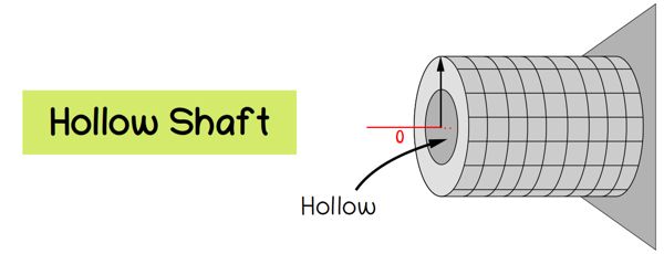
This significantly increases the value of J. This we have already stated that for circular shafts, J depends on the fourth power of the radius — which means even a small increase in radius leads to a very large increase in the polar moment of inertia.
Therefore, for the same torque, the stress developed in the shaft is lower. And at the same time, the shaft becomes stiffer — so it twists less.
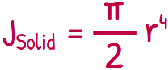
The polar moment of inertia for solid circular cross-section is :
and for the hollow circular cross-section :

Now, depending on how we design it, hollow shafts can give us two major advantages.
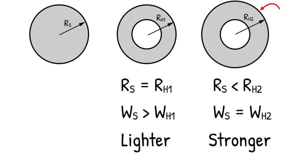
If we keep the outer diameter the same and remove material from the center, the shaft becomes much lighter — while still maintaining good strength. And even more interesting — for the same amount of material, a hollow shaft can actually be stronger and stiffer than a solid shaft. Because it places more material where it matters the most — near the outer surface, where the stress is highest.
So this is true engineering: it’s not just about using more material; it’s about using the material we have wisely.
Now, you might be wondering—once we’ve done all this math and calculated our Stress and our Angle of Twist, what do we actually do with those numbers?
In engineering, these calculations are used to design shafts that are both safe and functional.
First, we check the maximum shear stress. It should not exceed what the material can safely handle — otherwise the shaft may fail.
Second, we check the angle of twist. Because even if the shaft doesn’t break, too much twisting can still create problems. It can lead to misalignment in gears, unwanted vibrations, and loss of efficiency.
So in simple terms — one condition ensures the shaft doesn’t break and the other ensures it works properly.
And if either condition is not satisfied, engineers can modify the design — by increasing the size, choosing a better material, or using hollow shafts.