imagine you’re designing a simple bolt. This bolt will be holding two heavy steel plates together in a bridge or in a skyscraper. When those plates are subjected to heavy loads, all that force is transferred directly into our bolt. If the stress generated inside that bolt exceeds the material’s strength… it is going to fail.
Now interesting thing is, even if the forces are pulling or pushing in a perfectly straight line, the bolt usually doesn’t break straight across. If you look at a failed bolt, it tends to break along an inclined plane — it snaps at an angle.
As engineers we need to know at what angle will the bolt fail?
Quick Note : To make things easier, I’ve collected all the important formulas of Strength of Materials into one Formula sheet — you can check it below if you need it.
And to figure that out, we first need to understand how stress acts inside the bolt or in any other material. Stress doesn’t act the same in every direction and different planes experience different stresses.
We do have mathematical equations that can calculate the stress at any angle you can imagine.
But if we want to check the stress at 30°, then 45°, then 60° to find that ‘danger zone,’ we would have to solve these heavy equations over and over again. It’s exhausting and very easy to make a mistake.
So instead of doing that repeatedly, we use a very powerful and elegant method — Mohr’s Circle.
It’s basically a visual shortcut. It converts all those heavy equations into a simple diagram. And honestly, if you can draw a circle, you can find stress at any angle. And eventually it helps us understand where failure is most likely to occur.
So, let’s begin with the basics and look at what’s actually happening inside our bolt.
When we apply a force to a material, it fights back and develops an internal resistance to counteract that force. How much that resistant force is acting per unit area is called the Stress.
Mathematically it is defined as the force per unit area over which this force acts.

Now, in the material, this resistance or stress usually shows up as two different types —
1. Normal Stress
2. Shear Stress.
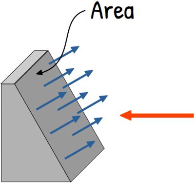
To visualize these stresses, let’s slice the object to show it’s area of cross-section.
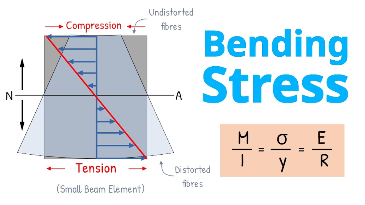
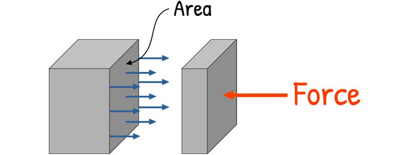
Normal stress is the type of stress that acts perpendicular, means at 90°, to the cross-section of the material.
Now if the direction of the internal force acting on this cross-section is outward, it will try to stretch the material and we call it Tensile Stress. On the other hand, if the direction of the internal force is inward, it tries to compress it and we call it Compressive Stress.
We write this normal stress, both tensile and compressive, as the Greek letter σ (sigma) and mathematically it is defined as force per unit area.

Now, if this internal force acts parallel to the cross-section of a material, it is called Shear stress. Shear means to cut or divide something into two parts, especially by sliding one part over the other.
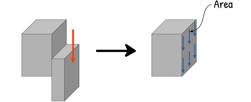
So, when a material experiences shear stress, the stress tries to move and slide part of it relative to the rest of the substance.
Shear stress is written as Greek letter τ and is also defined as force per unit area.

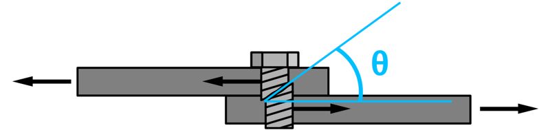
Now this is just one section — one vertical plane, on which we calculated both normal and shear stress developed. But we can slice the bolt at some angle, Say, at 30° or 45°.
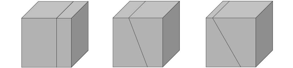
Even though the external force on the element hasn’t changed, the way the internal forces acts on that surface becomes different and also the area of that diagonal slice becomes larger too.
And because of that, the values of normal stress (σ) and shear stress (τ) also change as we change the orientation of the plane.
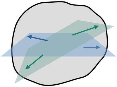
But as we can imagine there can be infinitely many such planes passing through a single point, each at a different angle.
Now among all these planes, we are especially interested in those where the stress becomes maximum, because on one of these planes if the stresses exceeds material’s capacity to handle, material fails along that plane. And that plane is called the Failure Plane.
But now comes a practical challenge — how do we analyze infinitely many planes?
Instead of dealing with the entire body, we simplify the problem. We zoom into a single point inside the material and imagine a very small element around it.
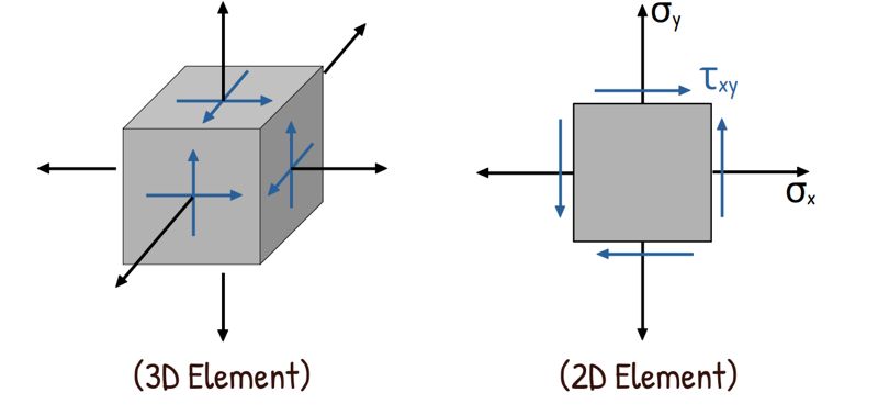
We show the stresses acting on this element from all directions as normal and shear stress. To simplify this even further, instead of three dimensional cube, let’s consider a two dimensional square.
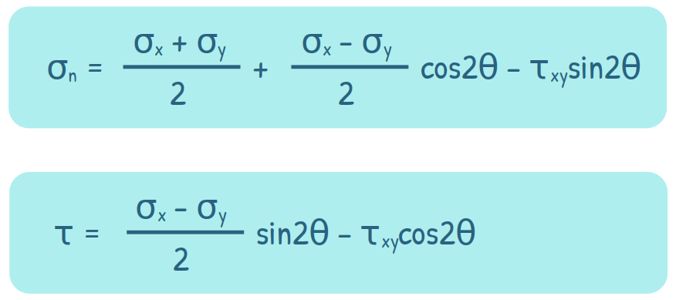
Let’s say the stresses acting on two mutually perpendicular planes of this square are σx, σy and τxy.
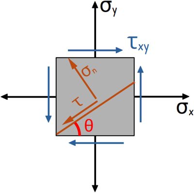
Now, mathematically, If we know the stresses acting on two mutually perpendicular planes, we can determine the stresses on any plane that is at any angle θ.
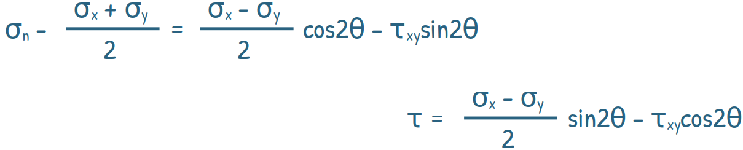
The normal and shear stress on this new plane can be given by these equations:
Don’t worry about memorizing these! They come from simply balancing the forces on that inclined plane.
However, looking at these long formulas, a German scientist and Civil Engineer, Christian Otto Mohr, realized these equations could be represented graphically as a simple circle. He then, developed an extremely useful device known as Mohr’s Circle of Stress.

This circle actually contains all the information about stress at every possible angle.
Instead of solving these equations again and again for different angles, Mohr showed that we can rearrange these equations to look like the standard formula for a circle.
First, we rewrite the equations after a little rearrangement
Next, we square both sides of the equations and add them together. This completely eliminates the θ:
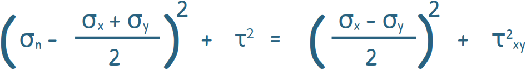
Now, if you remember your high school geometry, this is exactly the form of a circle equation
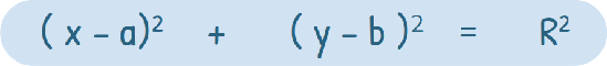

from this, we can clearly identify, the centre of the circle as this :

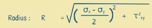
and its radius as this :
To draw Mohr’s Circle, we take normal stress on the horizontal axis and shear stress on the vertical axis.
We begin with two known stress points: (σx, τxy) and (σy, τyx).
We mark σx and σy on the normal stress axis, assuming that σx is greater than σy. Note that τxy and τyx are equal in magnitude but opposite in direction, so τxy = -τyx. So these two points lie vertically opposite each other.
We mark these points on the graph and connect these two points to form the diameter of the circle.
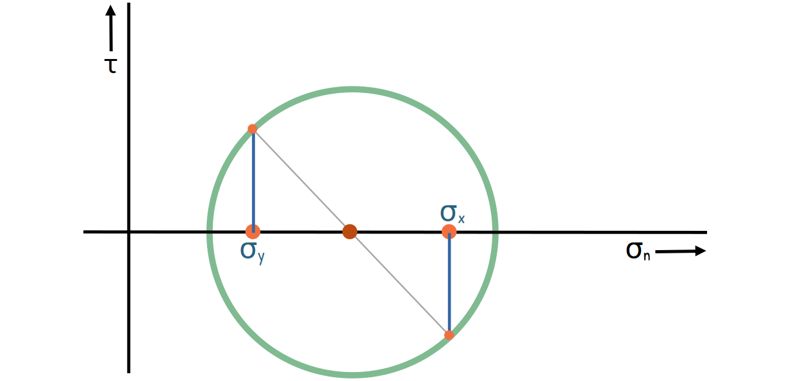
The midpoint of this line gives us the centre of the circle, which also lies on the normal stress axis.
With these points and the diameter, we complete the Mohr circle.
Now, take a moment to look at what we’ve just built. This isn’t just a geometric shape; it is a complete map of every single one of those infinite planes passing through that point in the material we mentioned earlier. Every single point on this circumference represents the exact combination of Normal and Shear stress for a different angle inside your material.
So instead of analyzing infinitely many planes one by one, we’ve captured all of them… in one diagram.
Now, using basic geometry, we can determine the centre and radius of this Mohr circle and its radius as this :
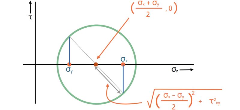
These are exactly the same values we obtained earlier from the equations.
Notice that on the circle, the points representing σx and σy are 180° apart. But in the actual material element, those planes are perpendicular, meaning they are 90° apart.
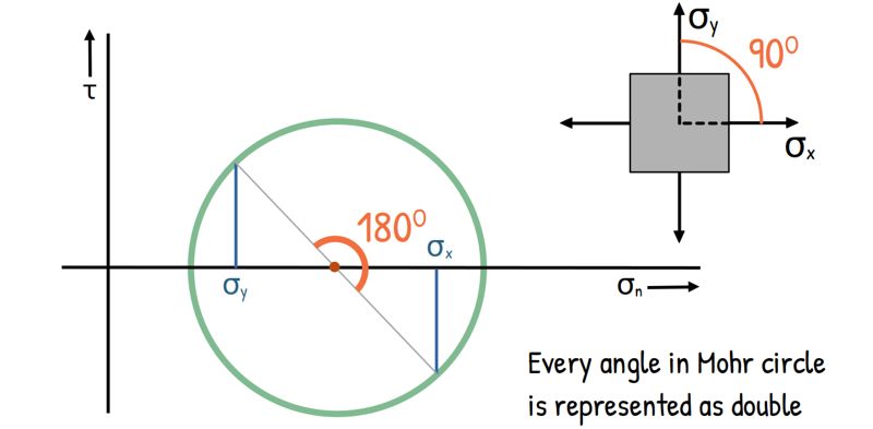
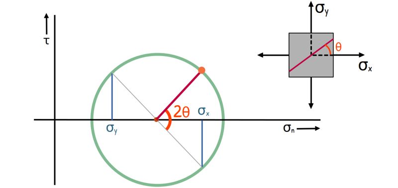
And this is how every angle in the Mohr circle is represented, it’s always double. Any plane in the material that is at an angle θ from the reference plane will be represented on the Mohr’s circle at a point that forms an angle of 2θ from the centre.
Also notice something very interesting in the Mohr’s circle. There are two points where the circle crosses the horizontal axis. At these points, the shear stress is zero.
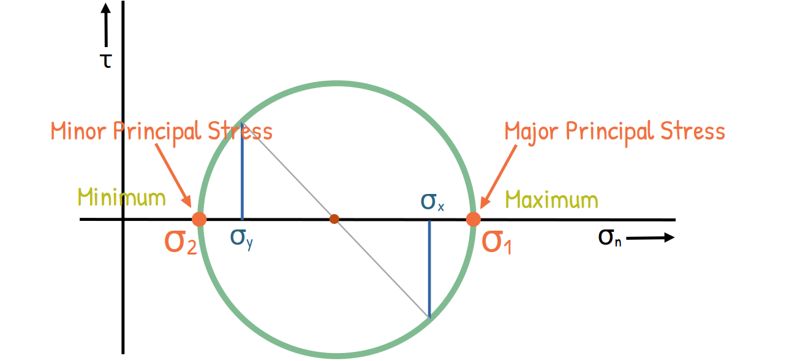
In real life, we actually find two planes in the material where shear stress is completely zero, and these two points on our circle represent those planes. Since, these points are 180° apart on the circle, we can infer, the corresponding planes in the material are perpendicular to each other. These planes are called principal planes, and the stresses on them are called principal stresses.
Also notice, these stresses are the highest and lowest normal stresses the material ever feels. They are denoted as σ1 and σ2, and are called major and minor principal stresses respectively.
In fact, in a real three-dimensional element, there are three such principal planes, mutually perpendicular to each other, on which the shear stress is zero. The normal stresses on those planes are denoted as σ₁, σ₂, and σ₃ and are called major, intermediate and minor principal stress respectively.
Now here’s another important observation.
If we look at the very top of our Mohr’s Circle, that point represents the absolute maximum shear stress acting on some plane inside our material. It’s clear from the geometry that this maximum shear stress (τmax) is exactly equal to the radius of the circle. As we move in either direction away from this peak, the shear stress values start to decrease.
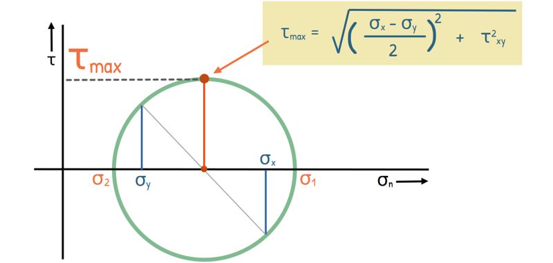
Therefore, the maximum shear stress that can occur on any plane in the material is equal to the radius of the Mohr circle.
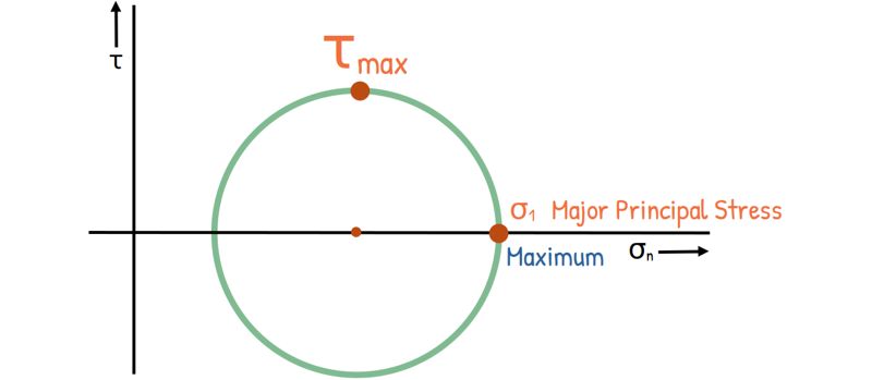
We can see that the point representing maximum shear stress makes a 90° angle at the center of the circle with our principal stress point. And since angles on Mohr’s circle are double the actual angle, the plane of maximum shear is actually inclined at 45° from the principal plane in the material.
So, maximum shear stress always acts on planes inclined at 45° to the principal planes.
Now, it might seem obvious to think that the material would fail exactly along the plane where either the normal stress is maximum or where shear stress is maximum.
But, surprisingly that is not always the case.
To predict the actual failure plane and the stresses at failure, engineers have developed several different theories. But let’s save that for another post.
Whether you are in Mechanical Engineering calculating the strength of a engine part, Geotechnical Engineering studying the stability of soil, or Structural Engineering designing a massive bridge, Mohr’s Circle is going to be your best friend. It’s more than just a graph; it’s a tool that helps us see the invisible forces inside our materials to make sure they stay safe.
If this made things clearer, here is the link to the formula sheet where all the important formulas are in one place.