Whether you’re a civil engineer constructing a skyscraper or simply an admirer of these towering structures, you might wonder: Can the soil beneath really handle all that enormous weight? Won’t the soil bulge or crack under such pressure?
Well, the soil’s ability to resist this cracking and shearing is called Shear Strength. We explored shear strength and how it’s described by the Mohr-Coulomb theory in our previous post.
We want to know the shear strength of the soil and how much load it can withstand before it shears or cracks, making the structure above unsafe. To determine the shear strength of the soil, scientists have developed different methods.
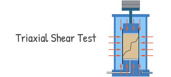
Today, we will dive into one of these methods: the Triaxial Shear Test.
In short, we take a soil sample and place it inside a triaxial apparatus. This machine applies pressure on the sample from all sides and an additional axial stress until it fails. The stress at which it fails tells us its shear strength. The apparatus uses fluid, usually water, to apply confining pressure, simulating real-world conditions. To understand the whole process in more detail, let’s dive deeper into the Triaxial Shear Test method.
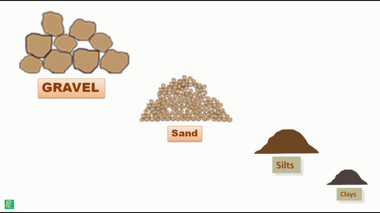
The triaxial Shear test is a crucial method used to determine the shear strength and stress-strain behaviour of soil samples. It can be performed on various types of soil, such as clay and sand, and the results help engineers understand how the soil will behave under different loading conditions.
The test is performed on a cylindrical sample of soil. Usually, the sample’s dimensions are kept at a length-to-diameter ratio of 2. For example, if the soil sample has a diameter of 50 mm, its length would be 100 mm.
To set up the test, we place the sample between two porous discs and position this assembly on the pedestal of the triaxial cell. We then attach a loading cap over the porous disc and encase the entire sample in a rubber membrane.
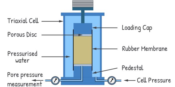
Next, we fill the cell with water at the required pressure. This applies an all-around pressure to the soil sample, which we call Cell pressure or Confining pressure, denoted as σc. We use a device attached to the cell to measure this pressure. The membrane protects the soil sample from being penetrated by the pressurized cell water.
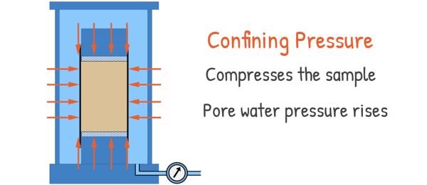
This confining pressure compresses the sample, causing the pore water pressure to rise. Water tries to leave the sample and consolidation of the sample begins. However, consolidation can only happen if we allow the water to drain out. For this purpose, we provide a drainage valve to the cell.
When this valve is closed, the water generates pore water pressure, which we can measure on a dial gauge. In this condition, the sample won’t consolidate because the water can’t leave the sample, resulting in no volume change.
But if we keep the valve open, the water flows out and doesn’t generate pressure. Soil begins to consolidate. In this case, we can’t measure the pore water pressure. Instead, we attach a volume change measurement system to the cell. The amount of water expelled from the sample is measured in a burette attached to the system. For a saturated soil sample, this measured volume of water is equal to the change in the volume of the soil sample.
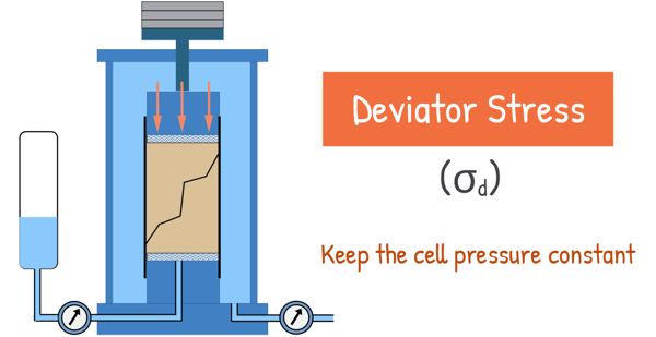
Once the consolidation process is complete, we keep the cell pressure constant and we gradually apply additional axial stress through a loading system called a ram. We slowly increase this axial stress until the sample fails. This additional axial stress is called Deviator stress and is denoted as σd.
Stresses and strains generated are noted and the test is repeated for another sample. But this time, the confining pressure is increased. The same procedure follows and corresponding deviator stress is measured.
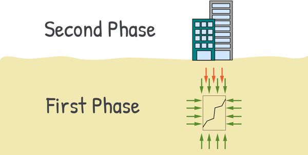
The first phase of the test, where the sample is subjected to confining pressure from all around, simulates the soil element’s environment in natural soil deposits. The second phase, where we apply an axial top load to the sample, simulates the condition where such a soil element is subjected to additional load, ultimately causing the soil to fail.
The axial strain generated in the sample because of the deviator stress is measured using a dial gauge attached to the loading ram. We collect data on the increasing deviator stress and its corresponding strain generated in the sample during the shearing phase. Hence, we can plot a graph between these stress and strain values.
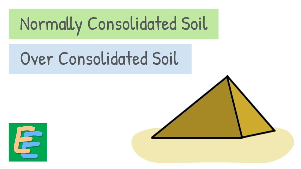
We get differnet kind of graphs for samples representing overconsolidated soil and normally consolidated soils. We already know that overconsolidated soils are those that have experienced higher loads in the past than they are experiencing now, while normally consolidated soils are those that are experiencing their highest load currently.
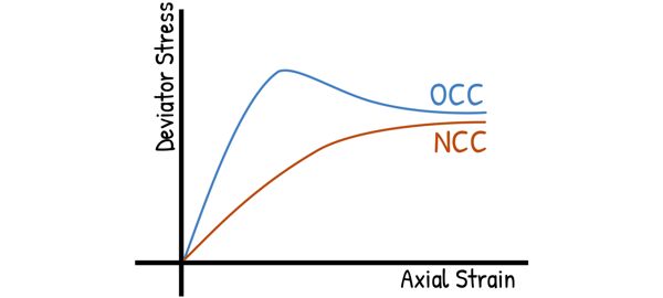
For overconsolidated soils (OCC), we observe a clear peak in the graph, followed by a drop in stress and eventual stabilization. The soil sample fails at this peak stress, which is also called the Failure stress. Beyond this point, the soil cannot take further load, but the strain keeps increasing.
For normally consolidated soils (NCC), we do not observe such a peak. Instead, the value of stress where the graph stabilizes is taken as the failure stress.
In triaxial test, as we mentioned, the sample is stressed in two phases: first, we apply cell pressure, and second, we apply deviator stress.
In the first phase, we can either keep the drainage line open, allowing the sample to consolidate, or close the line, keeping the sample unconsolidated.
In the second phase, we have similar options: we can either allow the water to drain out, which is called the drained condition, or prevent the water from escaping, which is the undrained condition.
So based on these drainage conditions, there are four possible scenarios for the test.
Unconsolidated Undrained
Unconsolidated Drained
Consolidated Undrained
Consolidated Drained
However, the ‘Unconsolidated Drained’ condition doesn’t make sense. It implies that we won’t allow the sample to consolidate in the first phase by keeping the water inside the cell, but will allow water to drain out in the second phase. The moment we allow the water to drain out, the sample will begin to consolidate.
Therefore, we can realistically test the soil in these three conditions only. In short, these conditions are called UU, CU, and CD. These drainage conditions are representative of certain real field situations.
At least three soil samples are tested in order to analyse the state of stress at the time of failure. At the time of failure, the confining stress and the axial stress (which is the confining stress plus the deviator stress) act normally on the surface of the sample.
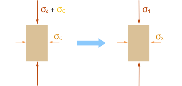
We can see, these are the maximum normal stresses acting on the soil sample as no other force is acting on the soil at any other angle. Therefore, they become the minor and major principal stresses, respectively.
What are major and minor principal stresses? To understand this better, please read the shear strength post, we have discussed these in detail there. In short, when a body is stressed, there exists three mutually perpendicular planes, on which shear stress is zero. These planes are called principal planes and stresses acting on them are called principal stresses.
Coming back to sample’s state of stress, the axial stress being the maximum and major principal stress, is denoted as σ1 and the confining stress is denoted as σ3. Using the data of these principal stresses at failure obtained from all three samples, we plot Mohr circles for each sample.
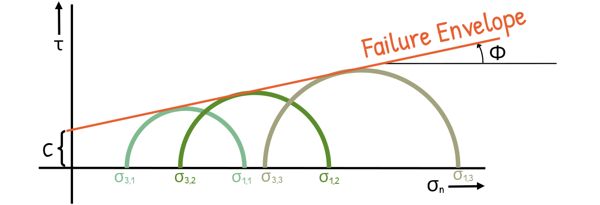
These circles show the stress conditions at failure for each sample. We then draw a common tangent to all three circles, which touches all three circles. This line is called the Failure envelope. The line is described as
τ = c + σ tanφ
this also, we have learned in our shear strength post.
The slope of this failure envelope gives us the angle of internal friction (φ), or angle of shearing resistance. Also the intercept this line makes at the stress axis is the cohesion (c).
It is important to note that σ1 and σ3 are the total stresses. In Unconsolidated Undrained and Consolidated Undrained tests, we don’t allow the water to escape, and we measure the pore water pressure. For these tests, we can also plot Mohr circles with effective stresses. We know Effective stress is simply the total stress minus the pore water pressure.
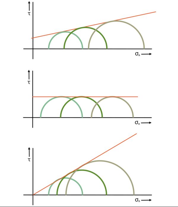
When we draw these curves for different drainage conditions, we get different sizes of Mohr circles and different positions of the failure envelope. We then extract the shear parameters from these graphs to complete our analysis.
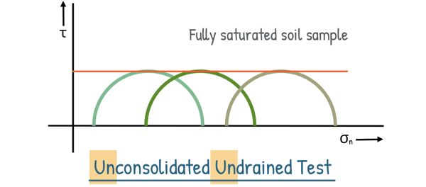
For example, in the Unconsolidated Undrained condition, where water drainage is not allowed during both stages of pressure application, if the soil sample is fully saturated, we get the following types of Mohr circles. All these circles have the same diameter, so in this case, the failure envelope—the line tangent to all the circles—will be a horizontal line.
The triaxial test significantly improves our ability to determine the shear strength of soil compared to the Direct Shear test.
The advantages of the Triaxial Shear Tests are :
1. This test accurately represents the real-life stress conditions that soil experiences in the field.
2. We have complete control over the drainage conditions during the test.
3. It allows us to easily measure changes in pore water pressure and volumetric changes, providing a thorough understanding of the soil’s behavior.
4. Sample can fail along its weakest plane, ensuring a natural failure mode.
5. Because we track the stress state at every stage leading up to failure, we can plot a Mohr circle for any shear stage.
6. The stress distribution across the failure plane is evenly distributed.
However, even after so many advantages of the Triaxial Shear Test, it has some limitations too.
1. The apparatus is quite bulky and expensive.
2. For drained tests the experiment takes a long time to complete compared to direct shear tests.
3. It is also challenging to accurately determine the cross-sectional area of the specimen at large strains.
4. We assume that the sample remains cylindrical at large strains, which may not always be the case.
5. The test only simulates axis-symmetrical problems, whereas real-world issues are often three-dimensional.
Well, Despite these drawbacks, the triaxial test is extremely useful. It is reliable and accurate in determining the shear characteristics of all types of soils under various drainage conditions.